- 您現(xiàn)在的位置:買(mǎi)賣(mài)IC網(wǎng) > PDF目錄372109 > SAA4700 (NXP SEMICONDUCTORS) VPS dataline processor PDF資料下載
參數(shù)資料
| 型號(hào): | SAA4700 |
| 廠商: | NXP SEMICONDUCTORS |
| 元件分類(lèi): | 消費(fèi)家電 |
| 英文描述: | VPS dataline processor |
| 中文描述: | SPECIALTY CONSUMER CIRCUIT, PDIP18 |
| 封裝: | 0.300 INCH, PLASTIC, DIP-18 |
| 文件頁(yè)數(shù): | 3/12頁(yè) |
| 文件大小: | 65K |
| 代理商: | SAA4700 |
March 1991
3
Philips Semiconductors
Preliminary specification
VPS dataline processor
SAA4700
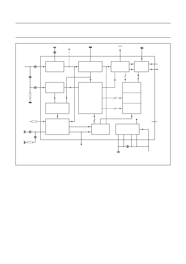
Fig.1 Block diagram and test circuit.
handbook, full pagewidth
MEH095
8.2 k
0.1
μ
F
external
reset
VP
22
nF
SYNC
SEPARATOR
FIELD SELECTOR
LINE 16 DECODER
I
2
C-BUS
CONTROL
OUTPUT
CONTROLLER
INPUT
CONTROLLER
40-BIT DATA
REGISTER
40-BIT
DATA LATCH
MULTIPLEXER
DATA
SLICER
CLOCK
REGENERATOR
PLL WITH
5 MHz VCO AND
PHASE DETECTOR
TIME BASE
clock pulse
REFERENCE
VOLTAGES
POWER-ON RESET
data
SAA4700
SCL
n.c.
SDA
4
5
6
8
18
9
8
to VP
75 k
(2%)
4.7
k
CVBS
CSO
4.7 nF
1 nF
(test line 16)
DAV
470 pF
4.7 nF
0.1
μ
F
2
5
6
11
12
7
AD = LOW
1
13
17
14
3
4
15
16
10
data
VCS
line 16
+
5 V
FUNCTIONAL DESCRIPTION
Dataline 16
The information in dataline 16
consists of fifteen 8-bit words; the
total information content is shown in
Table 1; and the organization of
transmitted bytes is shown in Table 2.
Out of the fifteen possible 8-bit words
the SAA4700 extracts words 5 and 11
to 14. The contents of these words
can be read via the built-in I
2
C-bus
interface. The circuit is fully
transparent, thus each bit is
transferred without modification with
only the sequence of words being
changed. Words 11 to 14
are transmitted first followed by
word 5.
By evaluating the sliced sync signal
the circuit can identify the beginning
of dataline 16 in the first field. The
dataline decoder stage releases the
start code detector. When a correct
start code is detected (for timing of
start code detection see Fig.3) words
5 and 11 to 14 are decoded, checked
for biphase errors and stored in a
register bank. If no biphase error has
occurred, the contents of the register
bank are transferred to a second
register bank by the data valid control
signal. If the system has been
addressed, this transfer will be
delayed until the next start or stop
condition of the I
2
C-bus has been
received.
The last bit of correct information on
the dataline remains available until it
is read via the I
2
C-bus. Once the
stored information has been read it is
considered to be no longer valid and
the internal new data flag is reset.
Subsequently, if the circuit is
addressed, the only VPS data that will
be sent back is ”FFF to F”. The same
conditions apply after power-up when
no data can be read out. New data is
available after reception of another
error-free dataline 16.
相關(guān)PDF資料 |
PDF描述 |
|---|---|
| SAA4945H | LIne MEmory noise Reduction IC LIMERIC |
| SAA4951 | RES 6.49K OHM 1/16W 0.5% 0402SMD |
| SAA4951WP | Memory controller |
| SAA4952WP | Memory controller |
| SAA4955 | 2.9-Mbit field memory |
相關(guān)代理商/技術(shù)參數(shù) |
參數(shù)描述 |
|---|---|
| SAA4700T | 制造商:PHILIPS 制造商全稱:NXP Semiconductors 功能描述:VPS dataline processor |
| SAA4945H | 制造商:PHILIPS 制造商全稱:NXP Semiconductors 功能描述:LIne MEmory noise Reduction IC LIMERIC |
| SAA4951 | 制造商:PHILIPS 制造商全稱:NXP Semiconductors 功能描述:Memory controller |
| SAA4951WP | 制造商:PHILIPS 制造商全稱:NXP Semiconductors 功能描述:Memory controller |
| SAA4952WP | 制造商:PHILIPS 制造商全稱:NXP Semiconductors 功能描述:Memory controller |
發(fā)布緊急采購(gòu),3分鐘左右您將得到回復(fù)。