- 您現(xiàn)在的位置:買賣IC網(wǎng) > PDF目錄372106 > SA575 (NXP Semiconductors N.V.) Low voltage compandor PDF資料下載
參數(shù)資料
| 型號(hào): | SA575 |
| 廠商: | NXP Semiconductors N.V. |
| 英文描述: | Low voltage compandor |
| 中文描述: | 低壓compandor |
| 文件頁數(shù): | 5/14頁 |
| 文件大小: | 102K |
| 代理商: | SA575 |

Philips Semiconductors
Product specification
SA575
Low voltage compandor
1997 Nov 07
5
voltage between Pins 4 and 9 will cause small offset error current in
the rectifier cell. This will affect the accuracy of the gain cell. This
can be improved by using an extra capacitor from the input to Pin 4
and eliminating the DC connection between Pins 4 and 9.
The expandor gain expression and the attack and release time
constant is given by Equation 1 and Equation 2, respectively.
4V
IN
(avg)
3.8k x 100
μ
A
where V
IN
(avg) = 0.95V
IN(RMS)
τ
R
=
τ
A
= 10k x C
RECT
= 10k x C4
Expandor gain =
Equation 2.
Equation 1.
COMPRESSOR
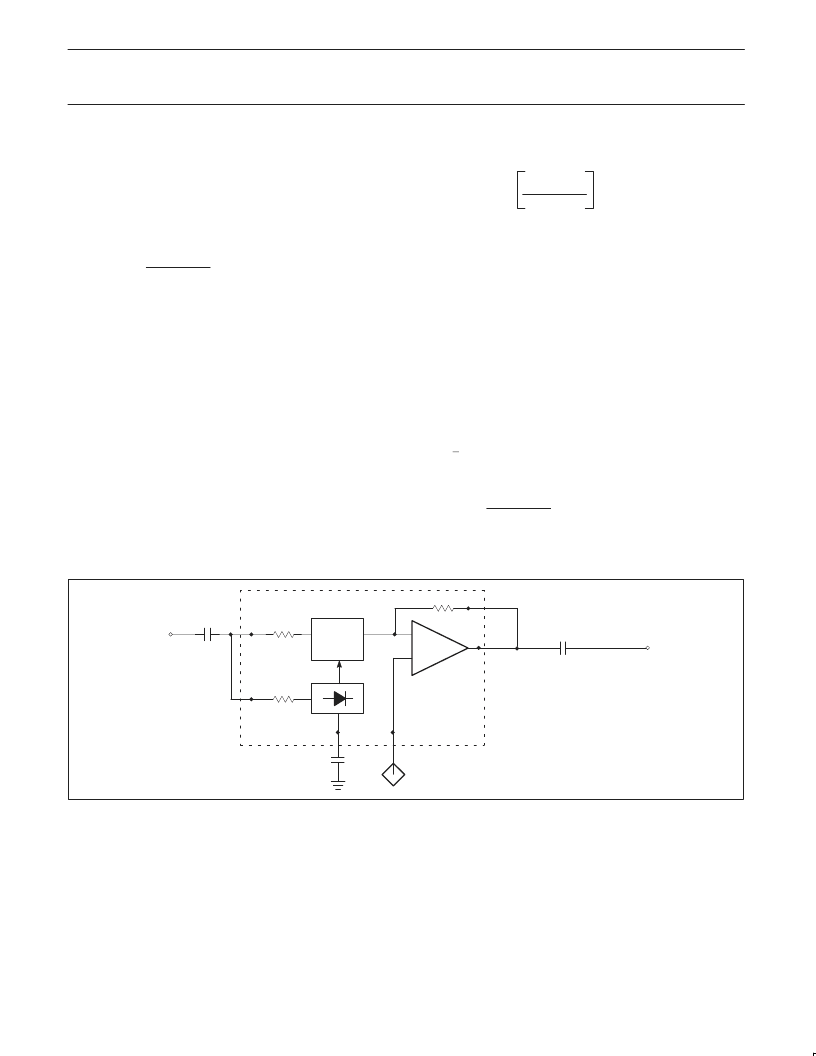
The typical compressor configuration is shown in Figure 4. In this
mode, the rectifier cell and variable gain cell are in the feedback
path. R6 and R7 provide the DC feedback to the summing amplifier.
The input is AC coupled through C12 and output is AC coupled
through C8. In a system with inputs and outputs AC coupled, C8
and C12 could be eliminated and only R6, R7, C7, and C13 would
be required. If the external components R6, R7 and C7 are
eliminated, then the output of the summing amplifier will motor-boat
in absence of signals or at extremely low signals. This is because
there is no DC feedback path from the output to input. In the
presence of an AC signal this phenomenon is not observed and the
circuit will appear to function properly.
The compressor gain expression and the attack and release time
constant is given by Equation 3 and Equation 4, respectively.
4V
IN
(avg)
3.8k x 100
μ
A
where V
IN
(avg) = 0.95V
IN(RMS)
τ
R
=
τ
A
= 10k x C
RECT
= 10k x C4
AUTOMATIC LEVEL CONTROL
The typical Automatic Level Control circuit configuration is shown in
Figure 5. It can be seen that it is quite similar to the compressor
schematic except that the input to the rectifier cell is from the input
path and not from the feedback path. The input is AC coupled
through C12 and C13 and the output is AC coupled through C8.
Once again, as in the previous cases, if the system input and output
signals are already AC coupled, then C12, C13 and C8 could be
eliminated. Concerning the compressor, removing R6, R7 and C7
will cause motor-boating in absence of signals. C
COMP
is necessary
to stabilize the summing amplifier at higher input levels. This circuit
provides an input dynamic range greater than 60dB with the output
within +0.5dB typical. The necessary design expressions are given
by Equation 5 and Equation 6, respectively.
1/2
Compressor gain =
Equation 3.
Equation 4.
4V
IN
(avg)
3.8k x 100
μ
A
τ
R
=
τ
A
= 10k x C
RECT
= 10k x C9
Equation 5.
Equation 6.
ALC gain =
2.2
μ
F
10
μ
F
10
μ
F
V
REF
G
Σ
EXP IN
EXP OUT
10k
C5
9
4
3.8k
5
C4
C3
10k
7
6
8
SR00705
Figure 3. Typical Expandor Configuration
相關(guān)PDF資料 |
PDF描述 |
|---|---|
| SA575D | Ceramic Multilayer Capacitor; Capacitance:5.6pF; Capacitance Tolerance:+/- 0.5 pF; Working Voltage, DC:50V; Dielectric Characteristic:C0G/NP0; Package/Case:0603; Series:VJ; Features:Multilayer Ceramic Chip Capacitor |
| SA575DK | Low voltage compandor |
| SA57608 | One-cell Lithium-ion battery protection with over/undercharge and overcurrent protection |
| SA57608XD | One-cell Lithium-ion battery protection with over/undercharge and overcurrent protection |
| SA576 | Low power compandor |
相關(guān)代理商/技術(shù)參數(shù) |
參數(shù)描述 |
|---|---|
| SA5751D | 制造商:未知廠家 制造商全稱:未知廠家 功能描述:Cell-Phone Circuit |
| SA5752 | 制造商:PHILIPS 制造商全稱:NXP Semiconductors 功能描述:Audio processor - companding, VOX and amplifier section |
| SA5752D | 制造商:PHILIPS 制造商全稱:NXP Semiconductors 功能描述:Audio processor-companding, VOX and amplifier section |
| SA5752DK | 制造商:PHILIPS 制造商全稱:NXP Semiconductors 功能描述:Audio processor - companding, VOX and amplifier section |
| SA5753 | 制造商:PHILIPS 制造商全稱:NXP Semiconductors 功能描述:Audio processor - filter and control section |
發(fā)布緊急采購,3分鐘左右您將得到回復(fù)。