- 您現(xiàn)在的位置:買賣IC網(wǎng) > PDF目錄373361 > SA24C1024LENFX (Electronic Theatre Controls, Inc.) The CAT24FC02 is a 2-kb Serial CMOS EEPROM internally organized as 256 words of 8 bits each PDF資料下載
參數(shù)資料
| 型號(hào): | SA24C1024LENFX |
| 廠商: | Electronic Theatre Controls, Inc. |
| 元件分類: | DRAM |
| 英文描述: | The CAT24FC02 is a 2-kb Serial CMOS EEPROM internally organized as 256 words of 8 bits each |
| 中文描述: | 該CAT24FC02是一個(gè)2 KB的EEPROM的國(guó)內(nèi)256個(gè)8位每字舉辦的串行CMOS |
| 文件頁數(shù): | 12/27頁 |
| 文件大?。?/td> | 680K |
| 代理商: | SA24C1024LENFX |
第1頁第2頁第3頁第4頁第5頁第6頁第7頁第8頁第9頁第10頁第11頁當(dāng)前第12頁第13頁第14頁第15頁第16頁第17頁第18頁第19頁第20頁第21頁第22頁第23頁第24頁第25頁第26頁第27頁
SA24C1024 Datasheet
SAIFUN
Background Information
(IIC Bus)
12
Extended IIC specification is an extension
of the Standard IIC specification, which
enables addressing of EEPROMs with
more than 15 Kbits of memory on an IIC
bus. The difference between the two
specifications is that the Extended IIC
specification defines two bytes of Array
Address information, while the Standard
IIC specification defines only one. All other
aspects are identical between the two
specifications. Using two bytes of the array
address, one Device/Page Block selection
bit (A1) in the Slave address byte and one
address signal (add16) in the Slave
address, it is possible to address up to 2
Mbits (2
8
2
8
2 2 8 = 2 Mbits) of
memory on an IIC bus.
Note that, due to format difference, it is not
possible to have both peripherals that
follow the Standard IIC specification (for
example, 16Kbit EEPROM) and peripherals
that follow the Extended IIC specification
(for example, 1024Kbit EEPROM) on a
common IIC bus.
The
bidirectional communication between a
transmitter and a receiver using a Clock
signal (SCL) and a Data signal (SDA).
Additionally, there is one Address signal
(A1) that collectively serves as "chip select
signal" to a device (for example, EEPROM)
on the bus.
IIC
bus
allows
synchronous
All communication on the IIC bus must be
started with a valid START condition (by
the Master), followed by transmittal (also
by the Master) of byte(s) of information
(Address/Data).
For
information
received,
receiver provides a valid acknowledge
(ACK) pulse to further continue the
communication (unless the receiver intends
to
discontinue
the
Depending on the direction of transfer
(Write or Read), the receiver can either be
a Slave or the Master. A typical IIC
communication concludes with a STOP
condition by the Master.
every
the
byte
addressed
of
communication).
Addressing an EEPROM memory location
involves sending a command string with
the following information:
[DEVICE TYPE]—[DEVICE/PAGE BLOCK
SELECTION
(including
ADDRESS
BIT
(add16)]—[R/WBIT]—
[ARRAY ADDRESS Byte #1]—[ARRAY
ADDRESS Byte #0]
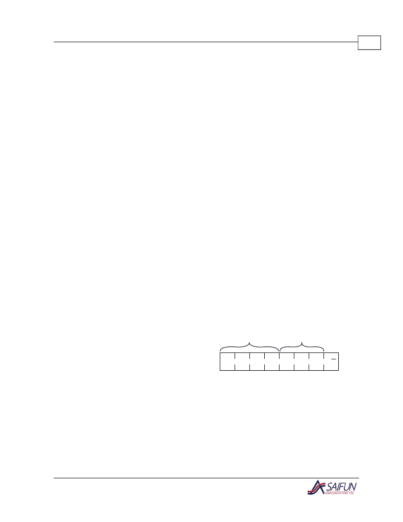
ARRAY
MSB
Slave Address
The Slave address is an 8-bit information
consisting of a Device Type field (4 bits), a
Device/Page Block selection field (3 bits)
and one Read/Write bit.
1
0
1
0
0
A1
Add16 R/W
(LSB)
Device Type
Identifier
Device/Page
Block Selection
Figure 9. Slave Address
相關(guān)PDF資料 |
PDF描述 |
|---|---|
| SA2512 | LED Lamp |
| SA2512B | LED Lamp |
| SA25C512 | The CAT24FC02 is a 2-kb Serial CMOS EEPROM internally organized as 256 words of 8 bits each |
| SA25C512HEMN | The CAT24FC02 is a 2-kb Serial CMOS EEPROM internally organized as 256 words of 8 bits each |
| SA25C512LMNX | The CAT24FC02 is a 2-kb Serial CMOS EEPROM internally organized as 256 words of 8 bits each |
相關(guān)代理商/技術(shù)參數(shù) |
參數(shù)描述 |
|---|---|
| SA24C1024LENX | 制造商:未知廠家 制造商全稱:未知廠家 功能描述:1024Kb EEPROM IIC |
| SA24C1024LMF | 制造商:未知廠家 制造商全稱:未知廠家 功能描述:1024Kb EEPROM IIC |
| SA24C1024LMFF | 制造商:未知廠家 制造商全稱:未知廠家 功能描述:1024Kb EEPROM IIC |
| SA24C1024LMFFX | 制造商:未知廠家 制造商全稱:未知廠家 功能描述:1024Kb EEPROM IIC |
| SA24C1024LMFX | 制造商:未知廠家 制造商全稱:未知廠家 功能描述:1024Kb EEPROM IIC |
發(fā)布緊急采購(gòu),3分鐘左右您將得到回復(fù)。