- 您現(xiàn)在的位置:買賣IC網(wǎng) > PDF目錄373355 > S82K-10024 (Electronic Theatre Controls, Inc.) Switch mode Power Supply PDF資料下載
參數(shù)資料
| 型號(hào): | S82K-10024 |
| 廠商: | Electronic Theatre Controls, Inc. |
| 英文描述: | Switch mode Power Supply |
| 中文描述: | 開關(guān)電源 |
| 文件頁數(shù): | 12/20頁 |
| 文件大小: | 318K |
| 代理商: | S82K-10024 |
L-16
Switch mode Power Supply
S82K
Operation
I
Undervoltage Alarm Indicator and Output Function
(All Models Except for S82K-24024/P24024)
If the output voltage at the output terminal drops to 75% to 90% of the rated voltage, the red indicator of the S82K (DC LOW indicator) will be lit.
In the case of the S82K-
@
09024/
@
10024/24024T, a voltage drop alarm will be output via the relay available in the models (DC LOW output).
Note:
This function detects the voltage at the output terminal of the Power Supply. To check the precise output voltage, measure the voltage at the
terminal of the load.
Note: 1.
The more the voltage at the output terminal drops, the darker both the green and red indicators will be.
2.
The relay contacts have a capacity of 0.1 A at 24 VDC.
3.
The red indicator will actually first light at a voltage between 75% and 90% of the rated voltage.
Engineering Data
I
Reference Value
I
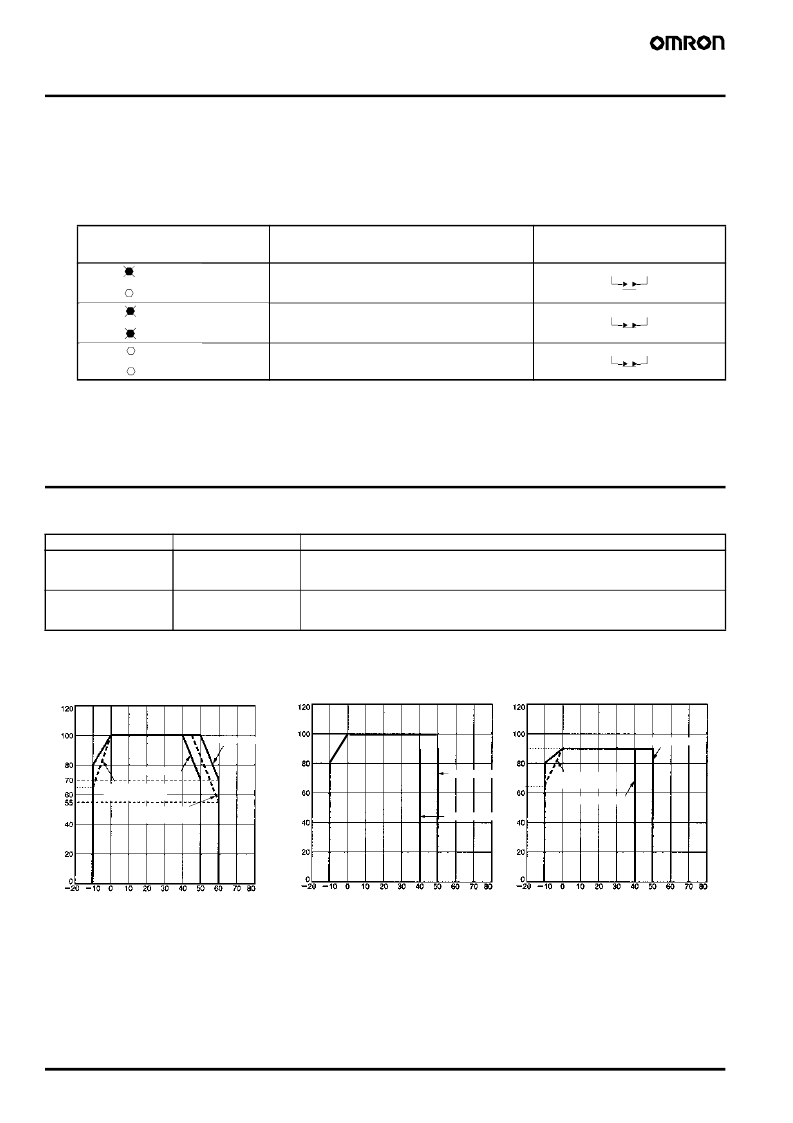
Derating Curve
3-/7.5-/15-/30-/50-/100-W Models
Single-Unit Operation
Indicator
Voltage
Operation of
@
09024/
@
10024/
24024T
’
s output (DC LOW output)
(see note 2)
If the voltage at the output terminal is more than 82% of
the rated voltage and operation is normal, the green in-
dicator will be lit and the red indicator will not be lit.
If the voltage at the output terminal drops to below 82%
of the rated voltage, the red indicator will be lit. (See
note 3.)
If the voltage at the output terminal approaches 0 V,
both the green and red indicators will not be lit.
Green:
DC ON
Red:
Green:
DC LOW
DC ON
Red:
Green:
DC LOW
DC ON
(see note 1)
Red:
DC LOW
Item
Value
Definition
Reliability (MTBF)
135,000 hrs min.
MTBF stands for Mean Time Between Failures, which is calculated according to the prob-
ability of accidental device failures, and indicates reliability of devices. Therefore, it does
not necessarily represent a life of the product.
The life expectancy indicates average operating hours under the ambient temperature of
40
°
C and a load rate of 50%. Normally this is determined by the life expectancy of the built-
in aluminum electrolytic capacitor.
Life expectancy
8 yrs. min.
65
65
90
L
Ambient temperature (
°
C)
Note:
When using the 7.5-W single-output
models within the input voltage range
between 90 and 110 VDC, the load
rate will become 90% or less.
L
Ambient temperature (
°
C)
L
Ambient temperature (
°
C)
Installation A
Installation A
Installation B
100-W Models with PFC
Parallel-Unit Operation
Installation B
Parallel-Unit Operation
100-W Models without PFC
Installation A
Installation B
S82K-P10024:
85-VAC input
S82K-03005
Installation A
S82K-P10024:
85-VAC input
相關(guān)PDF資料 |
PDF描述 |
|---|---|
| S82K-24024 | Switch mode Power Supply |
| S82K-24024T | Switch mode Power Supply |
| S82K-P09024 | Switch mode Power Supply |
| S82K-00305 | Switch mode Power Supply |
| S82K-00315 | Switch mode Power Supply |
相關(guān)代理商/技術(shù)參數(shù) |
參數(shù)描述 |
|---|---|
| S82K-10024(K) | 功能描述:DIN導(dǎo)軌式電源 RoHS:否 制造商:Mean Well 產(chǎn)品:Linear Supplies 商用/醫(yī)用:Commercial 輸出功率額定值:960 W 輸入電壓:180 VAC to 264 VAC, 254 VDC to 370 VDC 輸出端數(shù)量:1 輸出電壓(通道 1):48 V 輸出電流(通道 1): 輸出電壓(通道 2): 輸出電流(通道 2): 輸出電壓(通道 3): 輸出電流(通道 3): 尺寸:150 mm L x 110 mm W |
| S82K-10024 | 制造商:Omron Industrial Automation 功能描述:PSU DIN RAIL 24V 4.2A |
| S82K24024 | 制造商:OMRON AUTOMATION AND SAFETY 功能描述:POWER SUPPLY SW 24VDC 10A AC-IN |
| S82K-24024 | 功能描述:POWER SUPPLY SW 24VDC 10A AC-IN RoHS:是 類別:電源 - 外部/內(nèi)部(非板載) >> AC DC 轉(zhuǎn)換器 系列:S82K 產(chǎn)品培訓(xùn)模塊:MP Modular-Configurable AC-DC Power Supply 特色產(chǎn)品:Configurable Power Supplies 標(biāo)準(zhǔn)包裝:1 系列:MP |
| S82K24024T | 制造商:Omron Corporation 功能描述: |
發(fā)布緊急采購,3分鐘左右您將得到回復(fù)。