- 您現(xiàn)在的位置:買賣IC網(wǎng) > PDF目錄358385 > S401ERP75 1 A, 400 V, SCR, TO-92 PDF資料下載
參數(shù)資料
| 型號(hào): | S401ERP75 |
| 元件分類: | 晶閘管 |
| 英文描述: | 1 A, 400 V, SCR, TO-92 |
| 封裝: | ROHS COMPLIANT, GLASS, E PACKAGE-3 |
| 文件頁數(shù): | 6/9頁 |
| 文件大?。?/td> | 214K |
| 代理商: | S401ERP75 |
188
Revised: July 9, 2008
2008 Littelfuse, Inc.
Teccor
brand Thyristors
1 Amp Standard SCRs
Please refer to http://www.littelfuse.com for current information.
Specifications are subject to change without notice.
Sx01E & SxN1 Series
Physical Specifications
Environmental Specifications
Test
Specifications and Conditions
MIL-STD-750, M-1040, Cond A Applied
Peak AC voltage @ 125°C for 1008 hours
MIL-STD-750, M-1051,
100 cycles; -40°C to +150°C; 15-min
dwell-time
EIA / JEDEC, JESD22-A101
1008 hours; 320V - DC: 85°C; 85%
rel humidity
MIL-STD-750, M-1031,
1008 hours; 150°C
AC Blocking
Temperature Cycling
Temperature/
Humidity
High Temp Storage
Low-Temp Storage
1008 hours; -40°C
Thermal Shock
MIL-STD-750, M-1056
10 cycles; 0°C to 100°C; 5-min dwell-
time at each temperature; 10 sec (max)
transfer time between temperature
EIA / JEDEC, JESD22-A102
168 hours (121°C at 2 ATMs) and
100% R/H
Autoclave
Resistance to
Solder Heat
MIL-STD-750 Method 2031
Solderability
ANSI/J-STD-002, category 3, Test A
Lead Bend
MIL-STD-750, M-2036 Cond E
Terminal Finish
100% Matte Tin-plated
Body Material
UL recognized epoxy meeting flammability
classification 94V-0
Lead Material
Copper Alloy
Design Considerations
Careful selection of the correct device for the application’s
operating parameters and environment will go a long way
toward extending the operating life of the Thyristor. Good
design practice should limit the maximum continuous
current through the main terminals to 75% of the device
rating. Other ways to ensure long life for a power discrete
semiconductor are proper heat sinking and selection of
voltage ratings for worst case conditions. Overheating,
overvoltage (including dv/dt), and surge currents are
the main killers of semiconductors. Correct mounting,
soldering, and forming of the leads also help protect
against component damage.
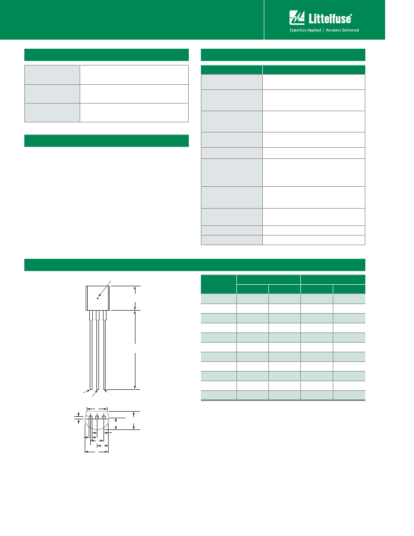
Dimensions – TO-92 (E Package)
Dimension
Inches
Millimeters
Min
Max
Min
Max
A
0.176
0.196
4.47
4.98
B
0.500
12.70
D
0.095
0.105
2.41
2.67
E
0.150
3.81
F
0.046
0.054
1.16
1.37
G
0.135
0.145
3.43
3.68
H
0.088
0.096
2.23
2.44
J
0.176
0.186
4.47
4.73
K
0.088
0.096
2.23
2.44
L
0.013
0.019
0.33
0.48
M
0.013
0.017
0.33
0.43
All leads insulated from case. Case is electrically nonconductive.
A
B
T
C
Measuring Point
Gate / PIN 2
Anode / MT2 / PIN 3
Cathode /
MT1 / PIN 1
E
H
G
F
D
K
J
L
M
相關(guān)PDF資料 |
PDF描述 |
|---|---|
| S4N1RP75 | 1 A, 400 V, SCR |
| S601EAP75 | 1 A, 600 V, SCR, TO-92 |
| S601ERP75 | 1 A, 600 V, SCR, TO-92 |
| S6N1RP75 | 1 A, 600 V, SCR |
| S420D | 1.5 A, SILICON, RECTIFIER DIODE, DO-214 |
相關(guān)代理商/技術(shù)參數(shù) |
參數(shù)描述 |
|---|---|
| S401W121-196 | 制造商: 功能描述: 制造商:undefined 功能描述: |
| S401W121-198 | 制造商: 功能描述: 制造商:undefined 功能描述: |
| S401W121-76 | 制造商: 功能描述: 制造商:undefined 功能描述: |
| S401W121-77 | 制造商: 功能描述: 制造商:undefined 功能描述: |
| S4020 | 功能描述:集管和線殼 2X2 SHUNT MULTIPLE POSITION RoHS:否 產(chǎn)品種類:1.0MM Rectangular Connectors 產(chǎn)品類型:Headers - Pin Strip 系列:DF50 觸點(diǎn)類型:Pin (Male) 節(jié)距:1 mm 位置/觸點(diǎn)數(shù)量:16 排數(shù):1 安裝風(fēng)格:SMD/SMT 安裝角:Right 端接類型:Solder 外殼材料:Liquid Crystal Polymer (LCP) 觸點(diǎn)材料:Brass 觸點(diǎn)電鍍:Gold 制造商:Hirose Connector |
發(fā)布緊急采購(gòu),3分鐘左右您將得到回復(fù)。