- 您現在的位置:買賣IC網 > PDF目錄31007 > S1242 321 A, SILICON, RECTIFIER DIODE, TO-244 PDF資料下載
參數資料
| 型號: | S1242 |
| 元件分類: | 整流器 |
| 英文描述: | 321 A, SILICON, RECTIFIER DIODE, TO-244 |
| 封裝: | TO-244, 2 PIN |
| 文件頁數: | 2/6頁 |
| 文件大?。?/td> | 211K |
| 代理商: | S1242 |

S1242
Bulletin PD-20017 02/01
2
www.irf.com
VBR
Cathode Anode
400
-
V
IR = 100A
Breakdown Voltage,
VFM
Max. Forward Voltage
-
1.10 1.35
V
IF = 160A
-
1.30 1.55
V
IF = 320A
-
1.00 1.20
V
IF = 160A, TJ = 125°C
IRM
Max.ReverseLeakageCurrent
-
2.0
12
A
VR = VR Rated
-
3.0
16
mA
TJ = 125°C, VR = 320V
CT
Junction Capacitance
-
370
500
pF
VR = 200V
LS
Series Inductance
-
5.0
-
nH
.
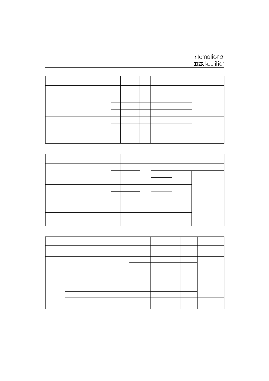
Electrical Characteristics (per Leg) @ TJ = 25°C (unless otherwise specified)
Parameters
Min Typ Max Units Test Conditions
From top of terminal hole to mounting plane
trr
ReverseRecoveryTime
-
45
-
ns
IF = 1.0A, di/dt = 200A/s, VR = 30V
trr1
-
90
140
TJ = 25°C
trr2
-
290
440
TJ = 125°C
IRRM1
Peak Recovery Current
-
8.7
20
A
TJ = 25°C
IRRM2
-18
30
TJ = 125°C
Qrr1
ReverseRecoveryCharge
-
420 1100
nC
TJ = 25°C
Qrr2
-
2600 7000
TJ = 125°C
di(rec)M /d/t1
-
300
-
A/s
TJ = 25°C
di(rec)M /d/t2
-
280
-
TJ = 25°C
Dynamic Recovery Characteristics @ TJ = 25°C (unless otherwise specified)
I
F = 160A
VR = 200V
diF /dt = 200A/s
Parameters
Min Typ Max Units Test Conditions
Parameters
Min
Typ
Max
Units
TJ
Max.JunctionTemperatureRange
-
- 55 to 150
°C
TStg
Max.StorageTemperatureRange
-
- 55 to 150
RthJC
Thermal Resistance, Junction to Case
Per Leg
-
0.24
°C/W
Thermal Resistance, Junction to Case
Per Module
-
0.12
K/W
RthCS
Thermal Resistance, Case to Heatsink
-
0.10
-
Wt
Weight
-
68 (2.4)
-
g (oz)
Mounting Torque (*)
30 (3.4)
-
40 (4.6)
lbf.in
Mounting Torque Center Hole
12 (1.4)
-
18 (2.1)
(N.m)
TerminalTorque
30 (3.4)
-
40 4.6)
Vertical Pull
-
80
lbf.in
2 inch Lever Pull
-
35
Thermal - Mechanical Characteristics
(*) Mounting surface must be smooth, flat, free or burrs or other protrusions. Apply a thin even film or thermal grease to
mounting surface. Gradually tighten each mounting bolt in 5-10lbf.in steps until desired or maximum torque limits are reached
See Fig. 1
See Fig. 2
See Fig. 3
See Fig. 5
See Fig. 6
See Fig. 7
See Fig. 8
相關PDF資料 |
PDF描述 |
|---|---|
| S1242PBF | 321 A, SILICON, RECTIFIER DIODE, TO-244 |
| S1242 | 321 A, SILICON, RECTIFIER DIODE, TO-244 |
| S14C03-8 | 300 W, BIDIRECTIONAL, 10 ELEMENT, SILICON, TVS DIODE |
| S14C24-8 | 300 W, BIDIRECTIONAL, 10 ELEMENT, SILICON, TVS DIODE |
| S14C05-8 | 300 W, BIDIRECTIONAL, 10 ELEMENT, SILICON, TVS DIODE |
相關代理商/技術參數 |
參數描述 |
|---|---|
| S124682-5R12-3 | 制造商:MISCELLANEOUS 功能描述: |
| S125 | 制造商:DIOTEC 制造商全稱:Diotec Semiconductor 功能描述:Surface Mount Si-Bridge Rectifiers |
| S-125 | 制造商:Limitor 功能描述:THERMAL FUSE S 125C |
| S1250FL-0 | 制造商:Thomas & Betts 功能描述:CABLE TIES |
| S1250FWL-0 | 制造商:Thomas & Betts 功能描述:CABLE TIES |
發(fā)布緊急采購,3分鐘左右您將得到回復。