- 您現(xiàn)在的位置:買賣IC網(wǎng) > PDF目錄373300 > RO2001 Analog IC PDF資料下載
參數(shù)資料
| 型號(hào): | RO2001 |
| 英文描述: | Analog IC |
| 中文描述: | 模擬IC |
| 文件頁(yè)數(shù): | 1/2頁(yè) |
| 文件大小: | 258K |
| 代理商: | RO2001 |
RF Monolithics, Inc.
RFM Europe
1999 by RF Monolithics, Inc. The stylized RFM logo are registered trademarks of RF Monolithics, Inc.
Phone: (972) 233-2903
Phone: 44 1963 251383
Fax: (972) 387-9148
Fax: 44 1963 251510
E-mail: info@rfm.com
http://www.rfm.com
RO2001-102199
Page 1 of 2
Electrical Characteristics
Characteristic
Absolute Frequency
Tolerance from 567.150 MHz
Sym
f
C
f
C
IL
Q
U
Q
L
T
O
f
O
FTC
|fA|
Notes
Minimum
567.050
Typical
Maximum
576.250
±100
7.0
Units
MHz
kHz
Center Frequency at 25 °C
2, 3, 4, 5
Insertion Loss
Quality Factor
2, 5, 6
6.0
9,600
4,800
71
f
c
+ 44
0.037
≤10
dB
Unloaded Q
50
Loaded Q
Turnover Temperature
Turnover Frequency
Frequency Temperature Coefficient
Absolute Value during the First Year
5, 6, 7
Temperature Stability
6, 7, 8
56
86
°C
kHz
ppm/°C
2
ppm/yr
M
μH
Frequency Aging
DC Insulation Resistance between Any Two Pins
RF Equivalent RLC Model
1
5
1.0
Motional Resistance
Motional Inductance
Motional Capacitance
Pin 1 to Pin 2 Static Capacitance
Transducer Static Capacitance
R
M
L
M
C
M
C
O
C
P
L
TEST
5, 7, 9
100
124
269.397
0.292315
1.1
0.8
72
fF
pF
pF
5, 6, 9
5, 6, 7, 9
2, 7
0.8
1.4
Test Fixture Shunt Induc-
Lid Symbolization
nH
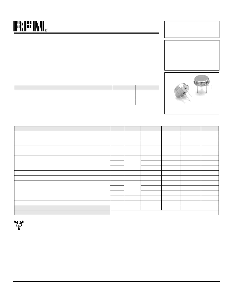
RFM RO2001
TO39-3 Case
Ideal for Baseband CATV Downconverter LOs
True One-Port Configuration
Quartz Stability
Rugged, Hermetic, Low-Profile TO39 Case
The RO2001 is a true one-port, surface-acoustic-wave (SAW) resonator in a low-profile TO39 case. It pro-
vides reliable, fundamental-mode, quartz frequency stabilization of fixed-frequency oscillators operating at
567.15 MHz. Although it is suitable for a wide variety of oscillator applications, this resonator is designed for
the second LO in CATV downconverters with the high IF at 612 MHz and the output at 45 MHz (baseband).
Absolute Maximum Ratings
Rating
Value
+10
±30
-40 to +85
Units
dBm
VDC
°C
CW RF Power Dissipation
DC Voltage Between Terminals
Case Temperature
567.15 MHz
SAW
Resonator
RO2001
CAUTION: Electrostatic Sensitive Device. Observe precautions for handling.
Notes:
1.
Frequency aging is the change in f
C
with time and is specified at +65°C or less.
Aging may exceed the specification for prolonged temperatures above +65°C.
Typically, aging is greatest the first year after manufacture, decreasing signifi-
cantly in subsequent years.
The center frequency, f
C
, is measured at the minimum insertion loss point,
IL
MIN
, with the resonator in the 50
test system (VSWR
≤
1.2:1). The shunt
inductance, L
TEST
, is tuned for parallel resonance with C
O
at f
C
. Typically, f
OS-
CILLATOR
or f
TRANSMITTER
is less than the resonator f
C
.
One or more of the following United States patents apply: 4,454,488 and
4,616,197 and others pending.
Typically, equipment designs utilizing this device require emissions testing and
government approval, which is the responsibility of the equipment manufacturer.
Unless noted otherwise, case temperature T
C
= +25°C±2°C.
The design, manufacturing process, and specifications of this device are subject
2.
3.
4.
5.
6.
to change without notice.
Derived mathematically from one or more of the following directly measured
parameters: f
C
, IL, 3 dB bandwidth, f
C
versus T
C
, and C
O
.
The turnover temperature, T
O
, is the temperature of maximum (or turnover) fre-
quency, f
O
. The nominal center frequency at any case temperature, TC, may be
calculated from: f = f
O
[1 - FTC (T
O
-T
C
)
2
].
This equivalent RLC model approximates resonator performance near the reso-
nant frequency and is provided for reference only. The capacitance C
O
is the
static (nonmotional) capacitance between pin1 and pin 2 measured at low fre-
quency (10 MHz) with a capacitance meter. The measurement includes case
parasitic capacitance with a floating case. For usual grounded case applications
(with ground connected to either pin 1 or pin 2 and to the case), add approxi-
mately 0.25pF to C
O
.
7.
8.
9.
相關(guān)PDF資料 |
PDF描述 |
|---|---|
| RO2002 | Analog IC |
| RO2003 | Analog IC |
| RO2021 | Analog IC |
| RO2023 | Analog IC |
| RO2023A-3 | Analog IC |
相關(guān)代理商/技術(shù)參數(shù) |
參數(shù)描述 |
|---|---|
| RO2002 | 制造商:未知廠家 制造商全稱:未知廠家 功能描述:Analog IC |
| RO2003 | 制造商:未知廠家 制造商全稱:未知廠家 功能描述:Analog IC |
| RO200BF1A103 | 功能描述:精度電位計(jì) ROT 200 B F 1 A 103 e1 RoHS:否 制造商:Bourns 產(chǎn)品:Precision Potentiometer 安裝風(fēng)格:Panel 線性: 錐度: 轉(zhuǎn)數(shù):3 元件類型:Wirewound 軸類型:Slotted 電阻:2 kOhms 端接類型:Solder Lug 電壓額定值: 容差:5 % |
| RO200BF1A202 | 功能描述:精度電位計(jì) ROT 200 B F 1 A 202 e1 RoHS:否 制造商:Bourns 產(chǎn)品:Precision Potentiometer 安裝風(fēng)格:Panel 線性: 錐度: 轉(zhuǎn)數(shù):3 元件類型:Wirewound 軸類型:Slotted 電阻:2 kOhms 端接類型:Solder Lug 電壓額定值: 容差:5 % |
| RO200BF1A502 | 功能描述:精度電位計(jì) ROT 200 B F 1 A 502 e1 RoHS:否 制造商:Bourns 產(chǎn)品:Precision Potentiometer 安裝風(fēng)格:Panel 線性: 錐度: 轉(zhuǎn)數(shù):3 元件類型:Wirewound 軸類型:Slotted 電阻:2 kOhms 端接類型:Solder Lug 電壓額定值: 容差:5 % |
發(fā)布緊急采購(gòu),3分鐘左右您將得到回復(fù)。