- 您現(xiàn)在的位置:買(mǎi)賣(mài)IC網(wǎng) > PDF目錄192245 > RMDM-31SBSM7-TL57A141 (ITT CANNON) 31 CONTACT(S), FEMALE, D MICROMINIATURE CONNECTOR, SOLDER, RECEPTACLE PDF資料下載
參數(shù)資料
| 型號(hào): | RMDM-31SBSM7-TL57A141 |
| 廠(chǎng)商: | ITT CANNON |
| 元件分類(lèi): | D-微型連接器 |
| 英文描述: | 31 CONTACT(S), FEMALE, D MICROMINIATURE CONNECTOR, SOLDER, RECEPTACLE |
| 封裝: | ROHS COMPLIANT |
| 文件頁(yè)數(shù): | 4/4頁(yè) |
| 文件大小: | 187K |
| 代理商: | RMDM-31SBSM7-TL57A141 |
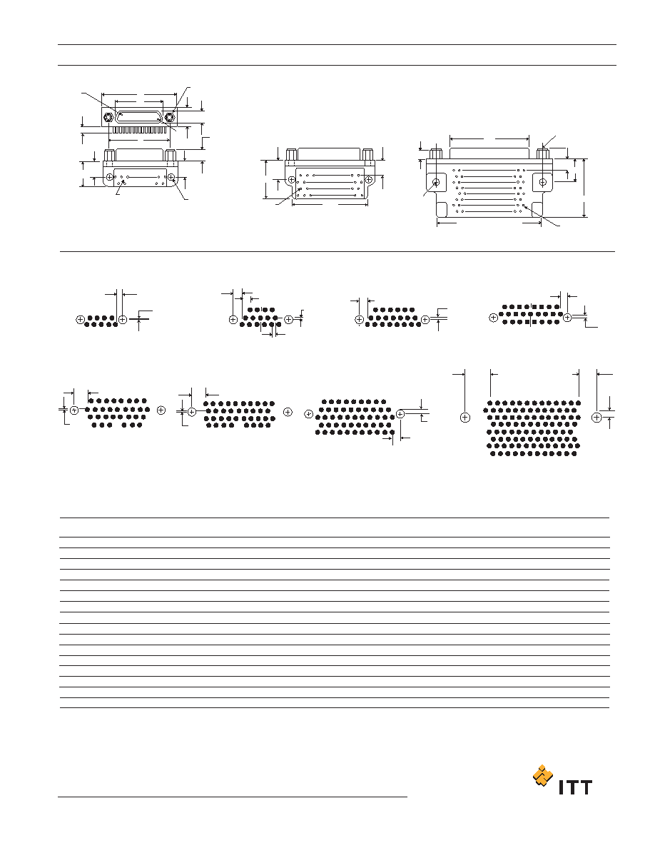
Micro-D PCB - .050" Contact Spacing
MDM-PCB
CBR (Condensed Board Right Angle) Series
21
www.ittcannon.com
Dimensions shown in inch (mm)
Specifications and dimensions subject to change
+
PCB Termination Arrangements (Viewed from bottom of connector, PCB solder side.)
Identification number shown for plug connector, use reverse order for socket connector.
54
2
1
3
5
7
24
10
12
14
16
17
19
21
23
25
27
29
30
18
20
22
26
28
31
2
4
6
8
9
11
13
15
1
3
5
7
24
10
12
14
16
17
19
21
23
25
27
29
30
32
34
36
18
20
22
26
28
31
33
35
37
2
4
6
8
9
11
13
15
1
3
5
7
24
10
12
14
16
17
19
21
23
25
27
29 46
43
41
30
32
34
36
37
38
39
40
44
45
42
47
48
49
50
51
18
20
22
26
28
31
33
35
2
4
6
8
9
11
13
15
1
3
5
7
24
10
12
14
16
17
19
21
23
25
27
29
37
39
41
43
45
47
49
51
28
30
32
34
36
38
40
42
44
46
48
50
53
55
57
59
61
63
65
67
69
71
73
75
52
54
56
58
60
62
64
66
68
70
72
74
76
78
80
82
84
86
88
90
92
94
96
98
100
77
79
81
83
85
87
89
91
93
95
97
99
18
20
22
26
31
33
35
2
4
6
8
9
11
13
15
98
3
7
6
2
4
5
7
86
12
3
1
9
1
2
3
4
5
6
7
8
9
10
11
17
14
21
23
25
20
22
24
19
18
16
15
13
12
10
11
13
14
15
.083
(2.11)
LAST
CAV.
.109 ± .015
(2.77 ± 0.38)
JACKPOST 2-56
UNC-2B TYP.
(Size 9-51)
.186 (4.72)
MAX.PLUG
.198 (5.03)
MAX. RECEPT.
.096 ± .005
(2.44 ± 0.31)
DIA.TYP.
(Size 9-51)
SEE
VIEW X
SEE
VIEW Y
SEE
VIEW W
G
* *
F
H
FOR 31: 1.085(27.56) MAX.
FOR 37: 1.185(30.10) MAX.
FOR 51: 1.225(31.12) MAX.
* *
.125 ± .005
(3.18 ± 0.31)
DIA. TYP.
.185
(4.70)MAX.
C
H
JACKPOST
#4-40 UNC 2B TYP.
G
F
1.815 (46.10) MAX.
100 VIEW
CAV.
#1
A
C
D
E
B
H
G
F
.020
(0.51)
.158 (4.00)
.020
(0.51)
.020
(0.51)
.183
(4.65)
.108
(2.73)
.050
(1.27)
.108
(2.73)
.100 (2.54)
TYP.
.050 (1.27)
TYP.
.020
(0.51)
.083
(2.11)
.020
(0.51)
.083 (2.11)
.020
(0.51)
.325 (8.26)
.275 (6.98)
.100 ± .005
(2.54 ± 0.13)
9 Contacts
View X
15 Contacts
View X
21 Contacts
View X
25 Contacts
View X
100 Contacts
View W
51 Contacts
View Y
37 Contacts
View Y
31 Contacts
View Y
NOTE: Standard lead termination is #24 AWG, solid copper,
solder or tin dripped.
*For jackpost, add letter "P" or "M7" for sizes 9-51, "M17" for size 100.
Part Number
By Shell Size
MDM-9PCBR*
MDM-9SCBR*
MDM-15PCBR*
MDM-15SCBR*
MDM-21PCBR*
MDM-21SCBR*
MDM-25PCBR*
MDM-25SCBR*
MDM-31PCBR*
MDM-31SCBR*
MDM-37PCBR*
MDM-37SCBR*
MDM-51PCBR*
MDM-51SCBR*
MDM-100PCBR*
MDM-100SCBR*
.785 (19.94)
.935 (23.75)
1.085 (27.56)
1.185 (30.10)
1.335 (33.91)
1.485 (37.72)
1.435 (36.45)
2.170 (55.12)
.565 (14.35)
.715 (18.16)
.865 (21.97)
.965 (24.51)
1.115 (28.32)
1.265 (32.13)
1.215 (30.86)
1.800 (45.72)
.334 (8.48)
.402 (10.21)
.484 (12.29)
.552 (13.97)
.634 (16.10)
.702 (17.83)
.734 (18.64)
.802 (20.37)
.884 (22.45)
.952 (24.18)
1.034 (26.26)
1.102 (27.99)
.984 (24.99)
1.052 (26.72)
1.384 (35.15)
1.508 (38.10)
.308 (7.82)
.351 (8.92)
.394 (10.01)
.185 (4.70)
.253 (6.43)
.185 (4.70)
.253 (6.43)
.185 (4.70)
.253 (6.43)
.184 (4.70)
.253 (6.43)
.185 (4.70)
.253 (6.43)
.185 (4.70)
.253 (6.43)
.228 (5.79)
.296 (7.52)
.271 (6.88)
.394 (10.01)
.420 (10.67)
.520 (13.21)
.650 (16.15)
1.000 (25.40)
.250 (6.35)
.300 (7.62)
.400 (10.16)
.230 (5.81)
.130 (3.30)
.150 (3.81)
.200 (5.08)
A
Max.
B
± .005 (.13)
G
± .010 (.25)
H
± .010 (.25)
C
Max.
D
Max.
E
Max.
F
Max.
All Termination Configurations .100 (2.54) x .100 (2.54) Grid Pattern, Offset .050 (1.27).
相關(guān)PDF資料 |
PDF描述 |
|---|---|
| RMDM-31SBSM7-TL57A172 | 31 CONTACT(S), FEMALE, D MICROMINIATURE CONNECTOR, SOLDER, RECEPTACLE |
| RMDM-31SBSM7-TL57A174 | 31 CONTACT(S), FEMALE, D MICROMINIATURE CONNECTOR, SOLDER, RECEPTACLE |
| RMDM-31SBSM7-TL57 | 31 CONTACT(S), FEMALE, D MICROMINIATURE CONNECTOR, SOLDER, RECEPTACLE |
| RMDM-31SBSM7-TL58A141 | 31 CONTACT(S), FEMALE, D MICROMINIATURE CONNECTOR, SOLDER, RECEPTACLE |
| RMDM-31SBSM7-TL58A172 | 31 CONTACT(S), FEMALE, D MICROMINIATURE CONNECTOR, SOLDER, RECEPTACLE |
相關(guān)代理商/技術(shù)參數(shù) |
參數(shù)描述 |
|---|---|
| RMDM-31SHA43B | 制造商:ITT Interconnect Solutions 功能描述:MICRO 31C S 180" RBW NI 制造商:ITT 功能描述:MICRO 31C S 180" RBW NI |
| RMDM-37PCBRP | 制造商:ITT Interconnect Solutions 功能描述:ROHS COMPLIANT MDM-37PCBRP - Bulk |
| RMDM-37PH001B | 制造商:ITT 功能描述:"MDM 37P 18"" YEL A174" 制造商:ITT Interconnect Solutions 功能描述:"MDM 37P 18"" YEL A174" |
| RMDM-37PH001P | 制造商:ITT Interconnect Solutions 功能描述:MICRO 37 M 18" YEL JACKPA174 |
| RMDM-37PH011B | 制造商:ITT 功能描述:"MICRO 37C P 36"" YEL NI" 制造商:ITT Interconnect Solutions 功能描述:"MICRO 37C P 36"" YEL NI" |
發(fā)布緊急采購(gòu),3分鐘左右您將得到回復(fù)。