- 您現(xiàn)在的位置:買賣IC網(wǎng) > PDF目錄368484 > RGF20A (智威科技股份有限公司) SURFACE MOUNT GLASS PASSIVATED JUNCTION FAST RECOVERY RECTIFIER PDF資料下載
參數(shù)資料
| 型號(hào): | RGF20A |
| 廠商: | 智威科技股份有限公司 |
| 英文描述: | SURFACE MOUNT GLASS PASSIVATED JUNCTION FAST RECOVERY RECTIFIER |
| 中文描述: | 表面貼裝玻璃鈍化結(jié)快速恢復(fù)整流 |
| 文件頁數(shù): | 1/2頁 |
| 文件大小: | 63K |
| 代理商: | RGF20A |

PATENTED
RGF20A THRU RGF20M
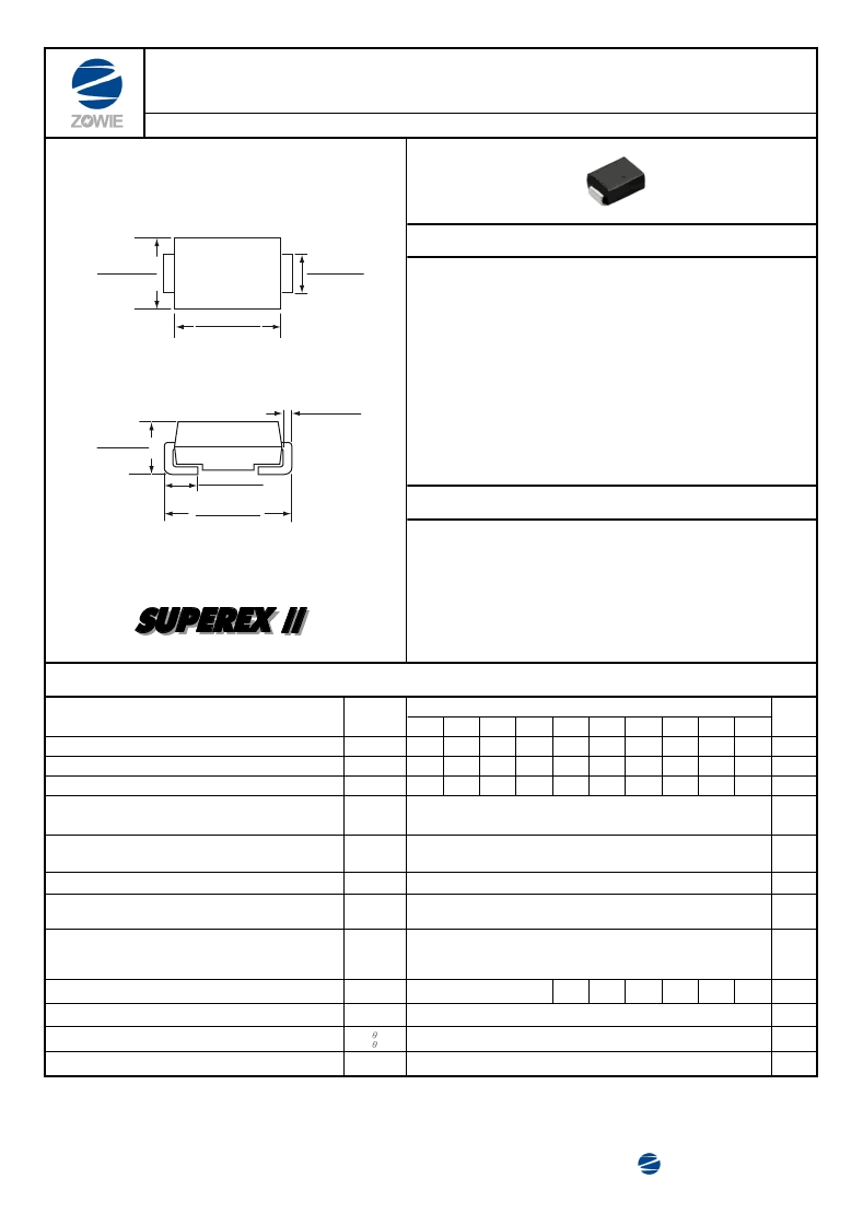
SURFACE MOUNT GLASS PASSIVATED JUNCTION FAST RECOVERY RECTIFIER
Reverse Voltage - 50 to 1000 Volts Forward Current - 2.0 Amperes
FEATURES
MECHANICAL DATA
* GPRC (Glass Passivated Rectifier Chip) inside
* Glass passivated cavity-free junction
* Ideal for surface mount automotive applications
* Fast switching for high efficiency
* Built-in strain relief
* Easy pick and place
* High temperature soldering guaranteed: 260
o
C/10 seconds,
at terminals
* Plastic package has Underwriters Laboratory Flammability
Classification 94V-0
Case :
JEDEC DO-214AA molded plastic over passivated chip
Terminals :
Solder plated , solderable per MIL-STD-750,
Method 2026
Polarity :
Color band denotes cathode end
Mounting Position :
Any
Weight :
0.003 ounes , 0.093 gram
MAXIMUM RATINGS AND ELECTRICAL CHARACTERISTICS
Ratings at 25
o
C ambient temperature
unless otherwise specified.
Maximum repetitive peak reverse voltage
Maximum average forward rectified current at T
A
=75
o
C
Peak forward surge current 8.3ms single half sine-wave
superimposed on rated load (JEDEC Method)
Maximum instantaneous forward voltage at 2.0 A
Maximum DC reverse current
at rated DC blocking voltage
T
A
=25
T
A
=125
T
A
=150
o
C
o
C
o
C
Maximum reverse recovery time (NOTE 1)
Typical junction capacitance (NOTE 2)
Typical thermal resistance (NOTE 3)
Operating junction and storage temperature range
SYMBOLS
V
RRM
I
(AV)
I
FSM
V
F
I
R
trr
C
J
R
JA
R
JL
T
J
,T
STG
RGF20
A
B
D
G
J
JA
K
KA
M
MA
50
100
200
400
600
600
800
800
1000
1000
2.0
65
1.3
5
30
100
150
250
150
500
300
500
300
35
55
18
-65 to +175
UNITS
Volts
Maximum RMS voltage
V
RMS
35
70
140
280
420
420
560
560
700
700
Volts
Maximum DC blocking voltage
V
DC
50
100
200
400
600
600
800
800
1000
1000
Volts
Volts
Maximum full load reverse current, full cycle
average , 0.375" (9.5mm) lead lengths at T
A
=55
o
C
I
R (AV)
100
uA
Amps
Amps
uA
nS
pF
o
C / W
o
C
NOTES :(1)Reverse recovery test condition : IF 0.5A, IR=1.0A, Irr=0.25A
(2)Measured at 1.0 MHz and applied reverse voltage of 4.0 Volts
(3)Thermal resistance from junction to ambient and from junction to lead P.C.B. mounted on 0.2 x 0.2" (5.0 x 5.0mm) copper pad areas.
Zowie Technology Corporation
REV. : 0
DO-214AA
*Dimensions in inches and (millimeters)
0.150(3.80)
0.130(3.30)
0.102(2.60)
0.079(2.00)
0.050(1.27)
0.030(0.76)
0.236(6.00)
0.197(5.00)
0.016(0.40)
0.006(0.15)
0.187(4.75)
0.167(4.24)
0.083(2.12)
0.077(1.95)
TM
相關(guān)PDF資料 |
PDF描述 |
|---|---|
| RGF20B | SURFACE MOUNT GLASS PASSIVATED JUNCTION FAST RECOVERY RECTIFIER |
| RGF20D | SURFACE MOUNT GLASS PASSIVATED JUNCTION FAST RECOVERY RECTIFIER |
| RGF20G | SURFACE MOUNT GLASS PASSIVATED JUNCTION FAST RECOVERY RECTIFIER |
| RGF20J | SURFACE MOUNT GLASS PASSIVATED JUNCTION FAST RECOVERY RECTIFIER |
| RGF20JA | SURFACE MOUNT GLASS PASSIVATED JUNCTION FAST RECOVERY RECTIFIER |
相關(guān)代理商/技術(shù)參數(shù) |
參數(shù)描述 |
|---|---|
| RGF20B | 制造商:JINANJINGHENG 制造商全稱:Jinan Jingheng (Group) Co.,Ltd 功能描述:FAST RECOVERY RECTIFIER |
| RGF20D | 制造商:JINANJINGHENG 制造商全稱:Jinan Jingheng (Group) Co.,Ltd 功能描述:FAST RECOVERY RECTIFIER |
| RGF20G | 制造商:JINANJINGHENG 制造商全稱:Jinan Jingheng (Group) Co.,Ltd 功能描述:FAST RECOVERY RECTIFIER |
| RGF20J | 制造商:ZOWIE 制造商全稱:Zowie Technology Corporation 功能描述:SURFACE MOUNT GLASS PASSIVATED JUNCTION FAST RECOVERY RECTIFIER |
| RGF20JA | 制造商:ZOWIE 制造商全稱:Zowie Technology Corporation 功能描述:SURFACE MOUNT GLASS PASSIVATED JUNCTION FAST RECOVERY RECTIFIER |
發(fā)布緊急采購,3分鐘左右您將得到回復(fù)。