- 您現(xiàn)在的位置:買賣IC網(wǎng) > PDF目錄385769 > RF2909 (RF MICRO DEVICES INC) 3V 915MHZ SPREAD-SPECTRUM TRANSMITTER IC PDF資料下載
參數(shù)資料
| 型號: | RF2909 |
| 廠商: | RF MICRO DEVICES INC |
| 元件分類: | 無繩電話/電話 |
| 英文描述: | 3V 915MHZ SPREAD-SPECTRUM TRANSMITTER IC |
| 中文描述: | TELECOM, CELLULAR, RF AND BASEBAND CIRCUIT, PDSO24 |
| 封裝: | SSOP-24 |
| 文件頁數(shù): | 2/8頁 |
| 文件大小: | 156K |
| 代理商: | RF2909 |
11-104
RF2909
Rev B1 010904
11
T
Standby Mode
Turn On/Off Time
0.15
Power Down “ON”
2
Power Down “OFF”
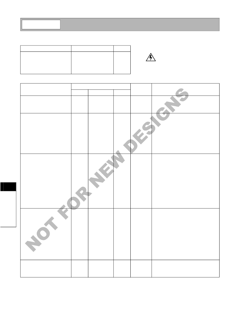
Absolute Maximum Ratings
Parameter
Supply Voltage
Power Down Voltage (V
PD
)
Input LO and RF Levels
Operating Ambient Temperature
Storage Temperature
Rating
-0.5 to +5.5
V
DD
+0.4
+6
-40 to +85
-40 to +150
Unit
V
DC
V
DC
dBm
°C
°C
Parameter
Specification
Typ.
Unit
Condition
Min.
Max.
Carrier Input (LO IN)
Frequency Range
Power Level
Input Impedance
Modulation Input
Frequency Range
Reference Voltage (V
REF
)
Modulation for P
OUT
Power (I & Q)
Maximum Modulation (I & Q)
Quadrature Phase Error
I/Q Amplitude Imbalance
Input Impedance
T=25°C, V
DD
=3.3V
Phase shift optimized for 915MHz
Differential
915MHz
100
902-928
-10
50
1100
MHz
dBm
DC
10
1.7
500
500
MHz
V
mV
p
50
source, I,Q=500mV
p-p
Differential, 1V
p
single ended
1
3
V
p
°
db
k
Differential, 1.5Vp single ended
5
.35
3
Differential
V
DD
=3.3V, LO power=-10dBm,
LOfrequency=915MHz, SSB, I/Q=1V
PP
sine wave, 100KHz
See Table I for control logic
RF Output
Digital Output Power
Output Impedance
Output VSWR
Second Harmonic Output
Other Harmonics Output
Sideband Suppression
Carrier Suppression
1, 10, 70
50
mW
1.5:1
With external matching (see app. schematic)
-25
-30
30
27
dBc
dBc
dB
dB
P
OUT
=10mW
Modulation DC offset can be externally
adjusted for optimum suppression. Carrier
suppression is then typically better than
40dB.
Output Level Control
Analog Power Control Range
Analog Power Control Voltage
(APC)
Analog Power Control Input
Current
Analog Power Output
Digital Power Output, High
Digital Power Output, Med
Digital Power Output, Low
PC 1/PC 2 “ON”
PC 1/PC 2 “OFF”
20
0
dB
V
3.6
Input voltage to pin 12 must be less than
3.6V or V
CC
(whichever is less).
1
μ
A
80
70
10
1
mW
mW
mW
mW
V
APC
=2.8V, PC1=“0”, PC2=“0”
APC=0V, PC 1=“0”, PC 2=“1”
APC=0V, PC 1=“1”, PC 2=“0”
APC=0V, PC 1=“0”, PC 2=“0”
Threshold Voltage
Threshold Voltage
1
2
1
μ
S
V
V
Threshold voltage; Part is turned “ON”
Threshold voltage; Part is turned “OFF”
1
Caution!
ESD sensitive device.
RF Micro Devices believes the furnished information is correct and accurate
at the time of this printing. However, RF Micro Devices reserves the right to
make changes to its products without notice. RF Micro Devices does not
assume responsibility for the use of the described product(s).
相關(guān)PDF資料 |
PDF描述 |
|---|---|
| RF2915 | 433/868/915MHZ FSK/ASK/OOK TRANSCEIVER |
| RF2917 | 433/868/915MHZ FM/FSK RECEIVER |
| RF2919 | 433/868/915MHZ ASK/OOK RECEIVER |
| RF2926 | UHF DUAL CONVERSION TRANSCEIVER |
| RF2938 | 2.4GHZ SPREAD-SPECTRUM TRANSCEIVER |
相關(guān)代理商/技術(shù)參數(shù) |
參數(shù)描述 |
|---|---|
| RF2915 | 制造商:RFMD 制造商全稱:RF Micro Devices 功能描述:433/868/915MHZ FSK/ASK/OOK TRANSCEIVER |
| RF2917 | 制造商:RFMD 制造商全稱:RF Micro Devices 功能描述:433/868/915MHZ FM/FSK RECEIVER |
| RF2919 | 制造商:RFMD 制造商全稱:RF Micro Devices 功能描述:433/868/915MHZ ASK/OOK RECEIVER |
| RF2926 | 制造商:RFMD 制造商全稱:RF Micro Devices 功能描述:UHF DUAL CONVERSION TRANSCEIVER |
| RF2926-000 | 制造商:TE Connectivity 功能描述:FEMTOSMDC005F-2 - Tape and Reel |
發(fā)布緊急采購,3分鐘左右您將得到回復(fù)。