- 您現(xiàn)在的位置:買賣IC網(wǎng) > PDF目錄2016 > QPO-2LZ-01 (Vicor Corporation)IC INTERFACE FILTER PDF資料下載
參數(shù)資料
| 型號: | QPO-2LZ-01 |
| 廠商: | Vicor Corporation |
| 文件頁數(shù): | 11/11頁 |
| 文件大小: | 0K |
| 描述: | IC INTERFACE FILTER |
| 標準包裝: | 20 |
| 系列: | Picor®, QUIETPOWER® |
| 其它名稱: | 1102-1094-5 |
Picor Corporation www.picorpower.com
QPO-2 Data Sheet Rev. 1.6 Page 9 of 11
Headroom Start-up Clamp Feature
This feature allows for pre-charging the Vref capacitance
to the level just below the steady state headroom voltage.
It reduces the time for the QPOout to reach the desired
regulation voltage and converter output overshoot that
results in the delay through the QPO filter during start-up.
The following formula can be used to calculate the RCP
resistor value to set the clamp at 90% of the final output
value. To set the clamp voltage to different percentages of
the output substitute the 0.90 with the desired factor.
The following is a summary of typical configurations that a
user can select for the QPO-2.
No slope adjust, no peak detect, fixed headroom,
attenuation vs headroom graph in Figure 7 apply
No slope adjust, peak detector enabled, headroom will
increase by the peak of the ripple amplitude
Slope adjust enabled, no peak detect, headroom will
decrease with the increase in load current
Slope adjust enabled, peak detector enabled,
headroom will vary with ripple amplitude and load
variations
The attributes of these features have been explained in
this datasheet. The optimum use of them requires an
understanding of the characteristics of the power supply
to be filtered.
RCP =
100k* (VQPOIN - 0.90 * VQPOOUT)
0.90 * VQPOOUT
0.1310
0.0880
0.0655
0.0880
15 places
0.0000
0.1000
0.3000
0.1000
0.3000
0.3970
0.4410
0.4
8
50
0.4
8
50
0.2000
0.0000
0.1000
0.3000
0.4410
0.3970
0.4850
0.0000
0.1000
0.3000
0.3970
0.4850
0.1500
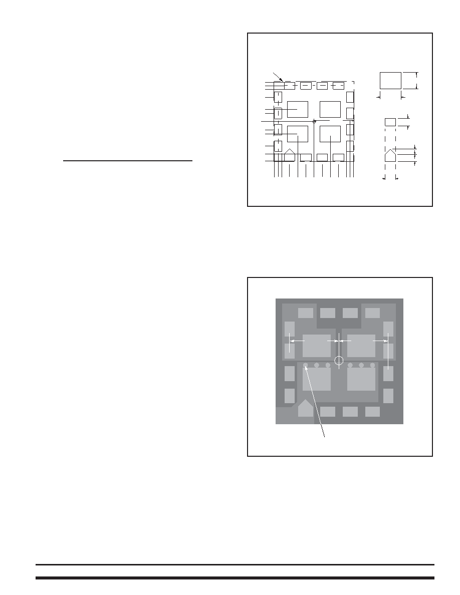
QPO Package Outline
QPO PCB Pad Pattern
(Top View)
4 places
0.492
0.2560
0.2060
Figure 11 - Recommended PCB receptor patterns. (dimensions in
inches)
QPO IN
QPO OUT
0.4410
Vias to ground plane
Figure 12 - Recommended PCB copper lands for low thermal resistance.
相關(guān)PDF資料 |
PDF描述 |
|---|---|
| QPO-2LZ | 0.3-5.5V 20A OUT RIP ATTENUATOR |
| RX-4801JE:UB | IC REAL TIME CLOCK MODULE |
| RX-5412SF: B3 PURE SN | IC REAL TIME CLOCK 24-SOP |
| RX-8801SA:UB3 PURE SN | IC REAL TIME CLOCK 14-SOP |
| SA555DX | IC OSC MONO TIMING 8-SOP |
相關(guān)代理商/技術(shù)參數(shù) |
參數(shù)描述 |
|---|---|
| QPP-003 | 制造商:未知廠家 制造商全稱:未知廠家 功能描述:60W, 869-894 MHz Class AB Power Stage |
| QPP-008 | 制造商:未知廠家 制造商全稱:未知廠家 功能描述:35W, 925-960MHz Class AB Driver Stage |
| QPP-015 | 制造商:未知廠家 制造商全稱:未知廠家 功能描述:QuikPAC Module Data |
| QPP-023 | 制造商:未知廠家 制造商全稱:未知廠家 功能描述:QuikPAC Module Data |
| QPP-029 | 制造商:未知廠家 制造商全稱:未知廠家 功能描述:QuikPAC Module Class AB Driver Stage |
發(fā)布緊急采購,3分鐘左右您將得到回復。