- 您現在的位置:買賣IC網 > PDF目錄368396 > PZ3128-S10BB1 Electrically-Erasable Complex PLD PDF資料下載
參數資料
| 型號: | PZ3128-S10BB1 |
| 英文描述: | Electrically-Erasable Complex PLD |
| 中文描述: | 電可擦除復雜可編程邏輯器件 |
| 文件頁數: | 6/18頁 |
| 文件大小: | 161K |
| 代理商: | PZ3128-S10BB1 |
R
XCR3128: 128 Macrocell CPLD
DS034 (v1.3) October 9, 2000
www.xilinx.com
1-800-255-7778
6
This product has been discontinued. Please see
for details.JTAG Testing Capability
JTAG is the commonly-used acronym for the Boundary
Scan Test (BST) feature defined for integrated circuits by
IEEE Standard 1149.1. This standard defines input/output
pins, logic control functions, and commands which facilitate
both board and device level testing without the use of spe-
cialized test equipment. BST provides the ability to test the
external connections of a device, test the internal logic of
the device, and capture data from the device during normal
operation. BST provides a number of benefits in each of the
following areas:
Testability
-
Allows testing of an unlimited number of
interconnects on the printed circuit board
-
Testability is designed in at the component level
-
Enables desired signal levels to be set at specific
pins (Preload)
-
Data from pin or core logic signals can be examined
during normal operation
Reliability
-
Eliminates physical contacts common to existing test
fixtures (e.g., "bed-of-nails")
-
Degradation of test equipment is no longer a
concern
-
Facilitates the handling of smaller, surface-mount
components
-
Allows for testing when components exist on both
sides of the printed circuit board
Cost
-
Reduces/eliminates the need for expensive test
equipment
-
Reduces test preparation time
-
Reduces spare board inventories
The Xilinx XCR3128's JTAG interface includes a TAP Port
and a TAP Controller, both of which are defined by the IEEE
1149.1 JTAG Specification. As implemented in the Xilinx
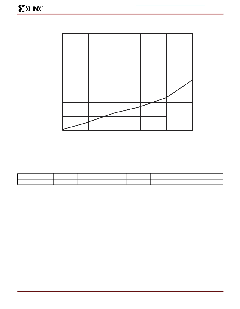
Figure 5: I
CC
vs. Frequency @ V
CC
= 3.3V, 25°C
Table 1: I
CC
vs. Frequency
(V
CC
= 3.3V, 25
°
C)
Frequency (MHz)
Typical I
CC
(mA)
0
1
20
12
40
24
60
35
80
46
100
63
.03
.06
FREQUENCY (MHz)
SP00471
0
20
40
60
80
0
20
40
60
80
100
120
140
I
(mA)
100
相關PDF資料 |
PDF描述 |
|---|---|
| PZ3128-S10BB1-S | Electrically-Erasable Complex PLD |
| PZ3128-S10BB2 | Electrically-Erasable Complex PLD |
| PZ3128-S10BE | Electrically-Erasable Complex PLD |
| PZ3128-S10BE-S | Electrically-Erasable Complex PLD |
| PZ3128-S10BP | Electrically-Erasable Complex PLD |
相關代理商/技術參數 |
參數描述 |
|---|---|
| PZ32146-0120 | 制造商:Foxconn 功能描述: |
| PZ37047-S01-A | 制造商:Foxconn 功能描述:Pga Socket, 370 Contacts, 19x19i, 0.05 Row Spacing, Pc Tail Terminal |
| PZ37047-S01-S | 制造商:Foxconn 功能描述:Pga Socket, 370 Contacts, 19x19i, 0.050 Row Spacing, Pc Tail Terminal |
| PZ3X1-15/16 | 制造商:Eclipse Tools 功能描述: |
| PZ-4-3 | 制造商:RICHARD MANNO 功能描述: |
發(fā)布緊急采購,3分鐘左右您將得到回復。