- 您現(xiàn)在的位置:買(mǎi)賣(mài)IC網(wǎng) > PDF目錄69258 > PTQA420025P2AD (TEXAS INSTRUMENTS INC) 1-OUTPUT 75 W DC-DC REG PWR SUPPLY MODULE PDF資料下載
參數(shù)資料
| 型號(hào): | PTQA420025P2AD |
| 廠商: | TEXAS INSTRUMENTS INC |
| 元件分類(lèi): | 電源模塊 |
| 英文描述: | 1-OUTPUT 75 W DC-DC REG PWR SUPPLY MODULE |
| 封裝: | LEAD FREE, DIP-8 |
| 文件頁(yè)數(shù): | 6/17頁(yè) |
| 文件大?。?/td> | 513K |
| 代理商: | PTQA420025P2AD |
第1頁(yè)第2頁(yè)第3頁(yè)第4頁(yè)第5頁(yè)當(dāng)前第6頁(yè)第7頁(yè)第8頁(yè)第9頁(yè)第10頁(yè)第11頁(yè)第12頁(yè)第13頁(yè)第14頁(yè)第15頁(yè)第16頁(yè)第17頁(yè)
www.ti.com
Adjusting the Output Voltage of the 100-W Rated PTQA Series of Isolated DC/DC Converters
R1 +
5.11 V
O (100 ) D%)
1.225 D%
*
511
D%
* 10.22 (kW)
(1)
(R2) + 5.11
100
D%
* 10.22 (kW)
(2)
I
O(max) +
V
O
I
O(rated)
V
A
(3)
L
O
A
D
Sense (–)
Sense (+)
+
(R2)
Adjust
Down
PTQA430xxxN
Sense(+)
Sense(–)
5
2
7
Adjust
8
6
4
1
3
+VI
VI
+VI
VI
CO
330
F
+VO
VO
+VO
VO
Remote
On/Off
R1
Adjust
Up
SLTS261B – MAY 2006 – REVISED NOVEMBER 2007
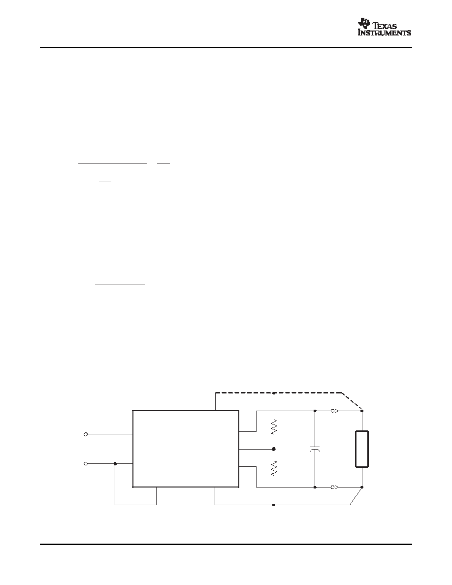
The output voltage adjustment of the PTQA series of isolated DC/DC converters follows the standard adopted by
popular 1/4-brick DC/DC converters. Adjustment is accomplished with a single external resistor that can adjust
the output voltage from –20% to +10% of the nominal set-point voltage. The placement of the resistor determines
the direction of adjustment, up or down, and the value of the magnitude of adjustment.
Adjust Up: To increase the output voltage add a resistor, R1, between VO Adjust (pin 6) and Sense(+) (pin 7).
Adjust Down: Add a resistor, (R2), between VO Adjust (pin 6) and Sense(–) (pin 5).
Refer to Figure 16 for the placement of the required resistor, R1 or (R2).
The values of R1 [adjust up], and (R2) [adjust down], can be calculated using the following formulas.
Where:
Δ% = Amount of adjustment in %
VO = Original set-point voltage
Notes:
1. Use only a single 1% resistor in either the R1 or (R2) location. Place the resistor as close to the converter as
possible.
2. If the output voltage is increased, the maximum load current must be derated according to the following
equation.
Where:
VO = Original set-point voltage
VA = Adjusted output voltage (measured between pins 8 and 4)
In any instance, the load current must not exceed the converter's maximum rated output current of 30 A.
3. The overvoltage threshold is fixed, and is set approximately 20% above the nominal output voltage. Adjusting
the output voltage higher reduces the voltage margin between the adjusted output voltage and the
overvoltage (OV) protection threshold. This could make the module sensitive to OV fault detection, as a
result of random noise and load transients.
Figure 16.
14
Copyright 2006–2007, Texas Instruments Incorporated
相關(guān)PDF資料 |
PDF描述 |
|---|---|
| PTQA420025N2AD | 1-OUTPUT 75 W DC-DC REG PWR SUPPLY MODULE |
| PTQA420025N2AZ | 1-OUTPUT 75 W DC-DC REG PWR SUPPLY MODULE |
| PTQA430050P2AZ | 1-OUTPUT 100 W DC-DC REG PWR SUPPLY MODULE |
| PTQA420025P2AZ | 1-OUTPUT 75 W DC-DC REG PWR SUPPLY MODULE |
| PTQA420033P2AS | 1-OUTPUT 100 W DC-DC REG PWR SUPPLY MODULE |
相關(guān)代理商/技術(shù)參數(shù) |
參數(shù)描述 |
|---|---|
| PTQA420025P2AS | 制造商:TI 制造商全稱(chēng):Texas Instruments 功能描述:100-W 48-V INPUT ISOLATED DC/DC CONVERTER |
| PTQA420025P2AZ | 制造商:TI 制造商全稱(chēng):Texas Instruments 功能描述:100-W 48-V INPUT ISOLATED DC/DC CONVERTER |
| PTQA420033N2AD | 制造商:TI 制造商全稱(chēng):Texas Instruments 功能描述:100-W 48-V INPUT ISOLATED DC/DC CONVERTER |
| PTQA420033N2AS | 制造商:TI 制造商全稱(chēng):Texas Instruments 功能描述:100-W 48-V INPUT ISOLATED DC/DC CONVERTER |
| PTQA420033N2AZ | 制造商:TI 制造商全稱(chēng):Texas Instruments 功能描述:100-W 48-V INPUT ISOLATED DC/DC CONVERTER |
發(fā)布緊急采購(gòu),3分鐘左右您將得到回復(fù)。