- 您現(xiàn)在的位置:買賣IC網(wǎng) > PDF目錄69255 > PTMA403033P2AZT (TEXAS INSTRUMENTS INC) 1-OUTPUT 10 W DC-DC REG PWR SUPPLY MODULE PDF資料下載
參數(shù)資料
| 型號(hào): | PTMA403033P2AZT |
| 廠商: | TEXAS INSTRUMENTS INC |
| 元件分類: | 電源模塊 |
| 英文描述: | 1-OUTPUT 10 W DC-DC REG PWR SUPPLY MODULE |
| 封裝: | ROHS COMPLIANT, DIP-6 |
| 文件頁數(shù): | 4/35頁 |
| 文件大小: | 1867K |
| 代理商: | PTMA403033P2AZT |
第1頁第2頁第3頁當(dāng)前第4頁第5頁第6頁第7頁第8頁第9頁第10頁第11頁第12頁第13頁第14頁第15頁第16頁第17頁第18頁第19頁第20頁第21頁第22頁第23頁第24頁第25頁第26頁第27頁第28頁第29頁第30頁第31頁第32頁第33頁第34頁第35頁
www.ti.com
R
TRIM(up) +
R
O
V
R
V
O * VSET
* RP (kW)
(1)
R
TRIM(dwn) +
R
O
V
O * VR
V
SET * VO
* RP (kW)
(2)
VO +
VO
4
5
6
TRIM
4
5
6
TRIM
RTRIM
CO
VO +
VO
VO +
VO
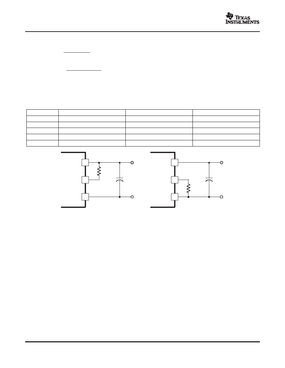
(a) TRIM DOWN
(b) TRIM UP
Thermal Considerations
On/Off Enable Controls
SLTS259B – FEBRUARY 2006 – REVISED MAY 2007
For other output voltages, the value of the required trim resistor may be calculated using Equation 1 to adjust
the voltage up or Equation 2 to adjust the voltage down.
Table 2 gives the required RTRIM equation constants for the converter model selected. To calculate the required
value of RTRIM, simply locate the applicable constants and substitute these into the formula along with the
desired output voltage.
Table 2. Trim Adjust Equation Constants
Constants
PTMA403033
PTMA402050
PTMA401120
VR (V)
1.24
2.50
RO ()
20
5.11
10
RP ()
1.0
2.05
5.11
VSET (V)
3.3
5.0
12.0
VO(V)
Desired Output Voltage
Figure 14. Output Voltage Adjustment
Airflow may be necessary to ensure that the module can supply the desired load current in environments with
elevated ambient temperatures. The required airflow rate is determined from the safe operating area (SOA). The
SOA is the area beneath the applicable airflow rate curve on the graph of temperature derating vs output
current. (See the Typical Characteristics.) Operating the converter within the SOA limits ensures that all the
internal components are at or below their stated maximum operating temperatures.
On/Off enable options include positive logic or negative logic. A positive logic device enables the module's
output when a logic high voltage is present on the Enable pin (pin 3) and disables the output with a logic low
voltage. A negative logic device disables the output when a logic high voltage is present on the Enable pin and
enables the output during a logic low voltage. See the Electrical Characteristics table for logic high and logic low
limits. The Enable pin is ideally controlled with an open-collector (or open-drain) discrete transistor. See
Figure 15 below for a typical On/Off Enable control circuit. For automatic start-up, the Enable pin should be left
open for a positive logic module and should be shorted to VI– (pin 2) for a negative logic module. Both inputs are
electrically referenced to VI– on the primary (input) side of the converter. Do not place an external pull-up
resistor on this input pin.
12
相關(guān)PDF資料 |
PDF描述 |
|---|---|
| PTMA402050P1AD | 1-OUTPUT 10 W DC-DC REG PWR SUPPLY MODULE |
| PTMA403033P2AS | 1-OUTPUT 10 W DC-DC REG PWR SUPPLY MODULE |
| PTMA402050P2AZ | 1-OUTPUT 10 W DC-DC REG PWR SUPPLY MODULE |
| PTMA401120N1AZT | 1-OUTPUT 10 W DC-DC REG PWR SUPPLY MODULE |
| PTMA403033N1AZ | 1-OUTPUT 10 W DC-DC REG PWR SUPPLY MODULE |
相關(guān)代理商/技術(shù)參數(shù) |
參數(shù)描述 |
|---|---|
| PTMB100A6 | 制造商:NIEC 制造商全稱:Nihon Inter Electronics Corporation 功能描述:IGBT MODULE Six-Pack 100A 600V |
| PTMB100A6C | 制造商:NIEC 制造商全稱:Nihon Inter Electronics Corporation 功能描述:IGBT SP series Six-Pack 100A 600V |
| PTMB100B12 | 制造商:NIEC 制造商全稱:Nihon Inter Electronics Corporation 功能描述:IGBT MODULE Six-Pack 100A 1200V |
| PTMB100B12C | 制造商:NIEC 制造商全稱:Nihon Inter Electronics Corporation 功能描述:IGBT SP series Six Pack 100A 1200V |
| PTMB100E6 | 制造商:NIEC 制造商全稱:Nihon Inter Electronics Corporation 功能描述:IGBT Module-Six Pack |
發(fā)布緊急采購,3分鐘左右您將得到回復(fù)。