- 您現(xiàn)在的位置:買賣IC網(wǎng) > PDF目錄69255 > PTH12050WAD (TEXAS INSTRUMENTS INC) 1-OUTPUT DC-DC REG PWR SUPPLY MODULE PDF資料下載
參數(shù)資料
| 型號: | PTH12050WAD |
| 廠商: | TEXAS INSTRUMENTS INC |
| 元件分類: | 電源模塊 |
| 英文描述: | 1-OUTPUT DC-DC REG PWR SUPPLY MODULE |
| 封裝: | ROHS COMPLIANT, DIP-6 |
| 文件頁數(shù): | 22/26頁 |
| 文件大小: | 1233K |
| 代理商: | PTH12050WAD |
第1頁第2頁第3頁第4頁第5頁第6頁第7頁第8頁第9頁第10頁第11頁第12頁第13頁第14頁第15頁第16頁第17頁第18頁第19頁第20頁第21頁當(dāng)前第22頁第23頁第24頁第25頁第26頁
www.ti.com
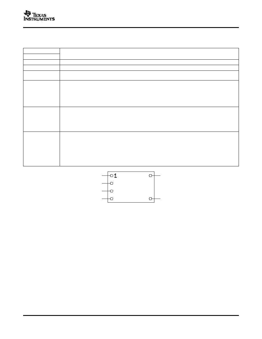
DEVICE INFORMATION
PTHXX050
(Top View)
1
5
2
3
4
6
SLTS214H – MAY 2003 – REVISED OCTOBER 2007
Terminal Functions
TERMINAL
DESCRIPTION
NAME
NO.
VI
3
The positive input voltage power node to the module, which is referenced to common GND.
VO
6
The regulated positive power output with respect to the GND node.
This is the common ground connection for the VI and VO power connections. It is also the 0-VDC reference for the
GND
1
control inputs.
A 1% resistor must be directly connected between this pin and GND (pin 1) to set the output voltage of the module
to a value higher than its lowest value. The temperature stability of the resistor should be 100 ppm/
°C (or better).
VOAdjust
5
The set-point range is 1.2 V to 5.5 V for W-suffix devices, and 0.8 V to 1.8 V for L-suffix devices. The resistor value
required for a given output voltage may be calculated using a formula. If left open circuit, the output voltage defaults
to its lowest value. For further information on output voltage adjustment, see the related application note.
The specification table gives the preferred resistor values for a number of standard output voltages.
The Inhibit pin is an open-collector/drain negative logic input that is referenced to GND. Applying a low-level ground
signal to this input disables the module’s output and turns off the output voltage. When the Inhibit control is active,
the input current drawn by the regulator is significantly reduced. If the Inhibit pin is left open circuit, the module
Inhibit
4
produces an output whenever a valid input source is applied. Do not place an external pull-up on this pin. For
power-up into a non-prebiased output, it is recommended that AutoTrack be utilized for On/Off control. See the
Application Information for additional details.
This is an analog control input that enables the output voltage to follow an external voltage. This pin becomes
active typically 20 ms after the input voltage has been applied, and allows direct control of the output voltage from
0 V up to the nominal set-point voltage. Within this range, the output follows the voltage at the Track pin on a
Track
2
volt-for-volt basis. When the control voltage is raised above this range, the module regulates at its set-point voltage.
The feature allows the output voltage to rise simultaneously with other modules powered from the same input bus.
If unused, the input should be connected to VI.
Note: Due to the under-voltage lockout feature, the output of the module cannot follow its own input voltage during
power up. For more information, see the related application note.
Copyright 2003–2007, Texas Instruments Incorporated
5
Product Folder Link(s): PTH12050W/L
相關(guān)PDF資料 |
PDF描述 |
|---|---|
| PTH12060LAST | 1-OUTPUT DC-DC REG PWR SUPPLY MODULE |
| PTH12060WAD | 1-OUTPUT DC-DC REG PWR SUPPLY MODULE |
| PTH12060LAS | 1-OUTPUT DC-DC REG PWR SUPPLY MODULE |
| PTH12060WAST | 1-OUTPUT DC-DC REG PWR SUPPLY MODULE |
| PTH12060WAS | 1-OUTPUT DC-DC REG PWR SUPPLY MODULE |
相關(guān)代理商/技術(shù)參數(shù) |
參數(shù)描述 |
|---|---|
| PTH12050WADT | 制造商:ARTESYN 制造商全稱:Artesyn Technologies 功能描述:DC-DC CONVERTERS POLA Non-isolated |
| PTH12050WAG | 制造商:Rochester Electronics LLC 功能描述: 制造商:Texas Instruments 功能描述: |
| PTH12050WAH | 功能描述:DC/DC轉(zhuǎn)換器 1.2 to 5.5V 6A 12V Input WideAdj Module RoHS:否 制造商:Murata 產(chǎn)品: 輸出功率: 輸入電壓范圍:3.6 V to 5.5 V 輸入電壓(標(biāo)稱): 輸出端數(shù)量:1 輸出電壓(通道 1):3.3 V 輸出電流(通道 1):600 mA 輸出電壓(通道 2): 輸出電流(通道 2): 安裝風(fēng)格:SMD/SMT 封裝 / 箱體尺寸: |
| PTH12050WAH | 制造商:POWER TRENDS 功能描述:IC DC/DC 12VIN 6A ADJ O/P 12050 |
| PTH12050WAHT | 制造商:ARTESYN 制造商全稱:Artesyn Technologies 功能描述:DC-DC CONVERTERS POLA Non-isolated |
發(fā)布緊急采購,3分鐘左右您將得到回復(fù)。