- 您現在的位置:買賣IC網 > PDF目錄368355 > PTH05000W Fully-integrated linear lighting ballast, IR21571, European version, 230VAC line, 36W/T8 lamp PDF資料下載
參數資料
| 型號: | PTH05000W |
| 英文描述: | Fully-integrated linear lighting ballast, IR21571, European version, 230VAC line, 36W/T8 lamp |
| 中文描述: | 6答:5 - V輸入寬輸出調節(jié)插入電源模塊 |
| 文件頁數: | 7/11頁 |
| 文件大小: | 286K |
| 代理商: | PTH05000W |
Application Notes
For technical support and more information, see inside back cover or visit www.ti.com
Output On/Off Inhibit
For applications requiring output voltage on/off control,
the PTH03000W & PTH05000W power modules in-
corporate an output on/off
Inhibit
control (pin 3). The
inhibit feature can be used wherever there is a require-
ment for the output voltage from the regulator to be
turned off.
The power module functions normally when the
Inhibit
pin is left open-circuit, providing a regulated output
whenever a valid source voltage is connected to
V
in
with
respect to
GND
.
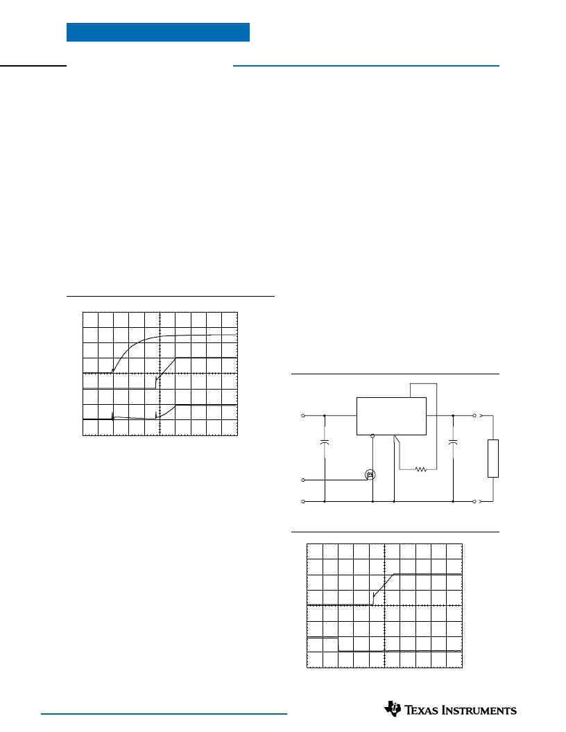
Figure 3-2 shows the typical application of the inhibit
function. Note the discrete transistor (Q
1
). The
Inhibit
control has its own internal pull-up to V
in
potential. An
open-collector or open-drain device is recommended to
control this input.
Turning Q
1
on applies a low voltage to the
Inhibit
control
pin and disables the output of the module. If Q
1
is then
turned off, the module will execute a soft-start power-up
sequence. A regulated output voltage is produced within
20 msec. Figure 3-3 shows the typical rise in the out-
put voltage, following the turn-off of Q
1
. The turn off of
Q
1
corresponds to the fall in the waveform, Q
1
V
gs
. The
waveforms were measured with a 5-A resistive load.
Figure 3-2
Figure 3-3
Power-Up Characteristics
When configured per their standard application, the
PTH03000 and PTH05000 series of power modules will
produce a regulated output voltage following the appli-
cation of a valid input source voltage. During power up,
internal soft-start circuitry slows the rate that the output
voltage rises, thereby limiting the amount of in-rush
current that can be drawn from the input source. The
soft-start circuitry introduces a short time delay (typi-
cally 10 ms) into the power-up characteristic. This is
from the point that a valid input source is recognized.
Figure 3-1 shows the power-up waveforms for a PTH05000W
(5-V input), with the output voltage set point adjusted for a
2-V output. The waveforms were measured with a 5-A
resistive load. The initial rise in input current when the
input voltage first starts to rise is the charge current drawn
by the input capacitors.
Figure 3-1
Current Limit Protection
The PTHxx000W modules protect against load faults
with a continuous current limit characteristic. Under a
load fault condition the output current cannot exceed
the current limit value. Attempting to draw current that
exceeds the current limit value causes the output voltage
to be progressively reduced. Current is continuously
supplied to the fault until it is removed. Upon removal of
the fault, the output voltage will promptly recover.
Thermal Shutdown
Thermal shutdown protects the module’s internal circuitry
against excessively high temperatures. A rise in tempera-
ture may be the result of a drop in airflow, a high ambient
temperature, or a sustained current limit condition. If
the junction temperature of the internal components
exceed 150 °C, the module will shutdown. This reduces
the output voltage to zero. The module will start up
automatically, by initiating a soft-start power up when
the sensed temperature decreases 10 °C below the thermal
shutdown trip point.
PTH03000 & PTH05000 Series
PTH05000W
V
IN
=5 V
1
4
5
2
3
C
IN
330 μF
(Required)
+
C
OUT
100 μF
(Optional)
+
Inhibit
GND
V
O
=2 V
4k87
0.1 W, 1 %
V
O
Adj
GND
Inhibit
V
IN
V
O
L
O
A
D
GND
Q
1
BSS138
Vo (1 V/Div)
Q1 Vgs
(10 V/Div)
HORIZ SCALE: 5 ms/Div
Vin (2 V/Div)
Vo (1 V/Div)
Iin (2 A/Div)
HORIZ SCALE: 5 ms/Div
相關PDF資料 |
PDF描述 |
|---|---|
| PTH12000W | 32W Fully-integrated linear lighting ballast, IR21571, U.S. version, 120VAC line, 32W/T8 lamp |
| PTH12030W | Universal Input Linear Fluorescent Ballast using the IR2167 |
| PTH8C16TBB101M | Universal Input Linear Fluorescent Ballast using the IR2166 |
| PTH8C16TBB221M | Mini-ballast for single 25W compact fluorescent ballast, European version with 230VACin |
| PTH8C16TBB330M | Intelligent Power Switch 1 Channel Low Side Driver in a SOT-223 Package |
相關代理商/技術參數 |
參數描述 |
|---|---|
| PTH05000WAD | 功能描述:DC/DC轉換器 6A 5VInput Wide-Out Adj Plug-in Pwr Mod RoHS:否 制造商:Murata 產品: 輸出功率: 輸入電壓范圍:3.6 V to 5.5 V 輸入電壓(標稱): 輸出端數量:1 輸出電壓(通道 1):3.3 V 輸出電流(通道 1):600 mA 輸出電壓(通道 2): 輸出電流(通道 2): 安裝風格:SMD/SMT 封裝 / 箱體尺寸: |
| PTH05000WAH | 功能描述:DC/DC轉換器 6A 5VInput Wide-Out Adj Plug-in Pwr Mod RoHS:否 制造商:Murata 產品: 輸出功率: 輸入電壓范圍:3.6 V to 5.5 V 輸入電壓(標稱): 輸出端數量:1 輸出電壓(通道 1):3.3 V 輸出電流(通道 1):600 mA 輸出電壓(通道 2): 輸出電流(通道 2): 安裝風格:SMD/SMT 封裝 / 箱體尺寸: |
| PTH05000WAH | 制造商:POWER TRENDS 功能描述:IC DC/DC 5VIN 6A ADJ O/P 5000 |
| PTH05000WAH | 制造商:Texas Instruments 功能描述:Supply Voltage Max.:5.5V |
| PTH05000WAS | 功能描述:DC/DC轉換器 6A 5VInput Wide-Out Adj Plug-in Pwr Mod RoHS:否 制造商:Murata 產品: 輸出功率: 輸入電壓范圍:3.6 V to 5.5 V 輸入電壓(標稱): 輸出端數量:1 輸出電壓(通道 1):3.3 V 輸出電流(通道 1):600 mA 輸出電壓(通道 2): 輸出電流(通道 2): 安裝風格:SMD/SMT 封裝 / 箱體尺寸: |
發(fā)布緊急采購,3分鐘左右您將得到回復。