- 您現(xiàn)在的位置:買賣IC網(wǎng) > PDF目錄368349 > PT7A4401C (Electronic Theatre Controls, Inc.) PT7A4401C T1/E1 System Synchronizer PDF資料下載
參數(shù)資料
| 型號(hào): | PT7A4401C |
| 廠商: | Electronic Theatre Controls, Inc. |
| 英文描述: | PT7A4401C T1/E1 System Synchronizer |
| 中文描述: | PT7A4401C的T1/E1系統(tǒng)同步 |
| 文件頁數(shù): | 8/27頁 |
| 文件大小: | 154K |
| 代理商: | PT7A4401C |
第1頁第2頁第3頁第4頁第5頁第6頁第7頁當(dāng)前第8頁第9頁第10頁第11頁第12頁第13頁第14頁第15頁第16頁第17頁第18頁第19頁第20頁第21頁第22頁第23頁第24頁第25頁第26頁第27頁
Data Sheet
PT7A4401C T1/E1 System Synchronizer
PT0108(09/02)
Ver:0
8
|||||||||||||||||||||||||||||||||||||||||||||||||||||||||||||||||||||||||||||||||||||||||||||||||||||||||||||||||||||||||||||||||||||||||||||||||||||||||||||||||||||||||||||||||||||||||||||||||||||||||||||||||||||||||||||||||||||||||||||||||||||||||||||||||||
Applications Information
Master Clock
The PT7A4401C uses either an external clock source or an
external crystal and a few passive components with its internal
oscillator as the master timing source.
In Free-Run State, the frequency tolerance of the PT7A4401C
output clocks are equal to the frequency tolerance of the tim-
ing source. In a given application, if an accurate Free-Run
State is not required, the tolerance of the master timing source
may be 100ppm. If required, the tolerance must be no worse
than 32 ppm.
The capture range of PT7A4401C must also be considered
when deciding the accuracy of the master timing source. The
sum of the accuracy of the master timing source and the cap-
ture range of the PT7A4401C will always equal 230ppm. For
example, if the master timing source is 100ppm, the capture
range will be 130ppm.
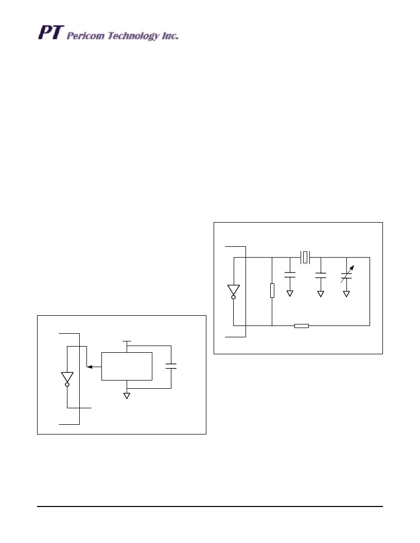
Clock Oscillator
If using an external clock source, its output pin should be
connected directly (not AC coupled) to the OSCi pin of the
PT7A4401C, and the OSCo pin can be left open as shown in
Figure 3 or connected as an output pin.
When selecting the clock oscillator, following specifications
should be considered. They are
- absolute frequency
- frequency change over temperature
- output rise and fall time
- output level
- duty cycle
Crystal Oscillator
If a crystal and passive components operating together with
the PT7A4401C oscillator are selected as the master timing
source, they should be connected as shown in Figure 4. It
should be possible to adjust the trimmer capacitor so that the
frequency is well within the 32 ppm tolerance; however, only
the proper specification of components will insure this toler-
ance over the necessary temperature range.
Figure 4. Crystal Oscillator Connection
Figure 3. Clock Oscillator Connection
+5V
20MHz OUT
GND
PT7A4401C
OSCi
OSCo
+5V
No Connection
0.1
μ
F
The crystal specification is as follows:
- Frequency:
- Tolerance:
- Oscillation Mode:
- Resonance Mode:
- Load Capacitance:
- Maximum Series Resistance:
-
Α
pproximate Drive Level:
20MHz
as required
Fundamental
Parallel
32pF
35
1mW
PT7A4401C
56pF
1M
20MHz
39pF
3-50pF
OSCi
OSCo
100
相關(guān)PDF資料 |
PDF描述 |
|---|---|
| PT7A4410J | T1/E1/OC3 System Synchronizer |
| PT7A4410LJ | T1/E1/OC3 System Synchronizer |
| PT7A8980 | 100V Quad N-Channel HEXFET Power MOSFET in a Power MLP package |
| PT7C4337 | Real-time Clock Module (I2C Bus) |
| PT7C4337PE | Real-time Clock Module (I2C Bus) |
相關(guān)代理商/技術(shù)參數(shù) |
參數(shù)描述 |
|---|---|
| PT7A4401CJ | 制造商:未知廠家 制造商全稱:未知廠家 功能描述:PT7A4401C T1/E1 System Synchronizer |
| PT7A4402B | 制造商:未知廠家 制造商全稱:未知廠家 功能描述:T1/E1 System Synchronizer? |
| PT7A4402BJE | 制造商:Pericom Semiconductor Corporation 功能描述:T1/E1 SYSTEM SYNCHRONIZER |
| PT7A4402L | 制造商:未知廠家 制造商全稱:未知廠家 功能描述:T1/E1 System Synchronizer? |
| PT7A4408 | 制造商:未知廠家 制造商全稱:未知廠家 功能描述:T1/E1/OC3 System Synchronizer? |
發(fā)布緊急采購,3分鐘左右您將得到回復(fù)。