- 您現(xiàn)在的位置:買賣IC網(wǎng) > PDF目錄368348 > PT7705N Advanced PFC and Ballast Control IC in a 16-Lead SOIC Package; A IRS2168DSPBF with Standard Packaging PDF資料下載
參數(shù)資料
| 型號: | PT7705N |
| 元件分類: | 基準(zhǔn)電壓源/電流源 |
| 英文描述: | Advanced PFC and Ballast Control IC in a 16-Lead SOIC Package; A IRS2168DSPBF with Standard Packaging |
| 中文描述: | 開關(guān)電源控制器 |
| 文件頁數(shù): | 4/5頁 |
| 文件大?。?/td> | 202K |
| 代理商: | PT7705N |
For technical support and more information, see inside back cover or visit www.ti.com/powertrends
Application Notes
Using the Standby Function on the “Big Hammer”
Programmable ISR Series
For applications requiring output voltage On/Off con-
trol, the PT7705 “Big Hammer” ISRs incorporate a standby
function
1
. This feature may be used for power-up/shutdown
sequencing, and to change the output voltage while input
power is applied.
See related notes:
“Pin-coded Output Volt-
age Adjustment on the ‘Big Hammer’ Series ISRs.”
The standby function is provided by the
STBY*
control,
pin 5. If pin 5 is left open-circuit the regulator operates
normally, providing a regulated output whenever a valid
supply voltage is applied to V
(pins 7-11) with respect to
GND (pins 13-19). Connecting pin 5 to ground
2
will set
the regulator output to zero volts
3
. This places the regula-
tor in standby mode, and reduces the input current to
typcially 45mA (75mA max). If a ground signal is applied to
pin 5 prior to power-up, the regulator output will be held at
zero volts during the period that input power is applied.
The standby input must be controlled with an open-
collector (or open-drain) discrete transistor (See Figure 1).
Table 1 gives the threshold requirements.
Table 1 Inhibit Control Threshold
2
Parameter
Min
Max
Disable (VIL)
–0.1V
0.3V
Notes:
1. The Standby/Inhibit control logic is similar for all Power
Trends’ modules, but the flexibility and threshold
tolerances will be different. For specific information on
this function for other regulator models, consult the
applicable application note.
2. The Standby input on the PT7705 regulator series must be
controlled using an open-collector (or open-drain) discrete
transistor.
Do Not
use a pull-up resistor. The control input
has an open-circuit voltage of about 1.5Vdc. To set the
regulator output to zero, the control pin must be “pulled”
to less than 0.3Vdc with a low-level 0.1mA sink to ground.
3. When placed in the standby mode, the regulator output
discharges the output capacitance with a low impedance to
ground. If an external voltage is applied to the output, it
will sink current and possibly over-stress the part.
4. The turn-off time of Q
, or rise time of the standby input
is not critical on the PT7705 series. Turning Q
off slowly,
over periods up to 100ms, will not affect regulator
operation. However, a slow turn-off time will increase
both the initial delay and rise-time of the output voltage.
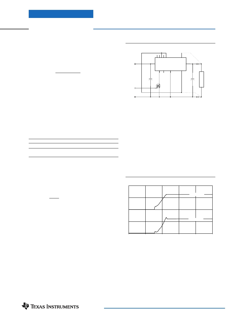
Figure 1
Turn-On Time:
Turning Q
in Figure 1 off, removes the low-
voltage signal at pin 5 and enables the output. Following a
brief delay of 5-10ms, the output voltage of the PT7705 series
regulators rise to full regulation within 15ms
4
. Figure 2 shows
the typical output voltage waveform of a PT7705 following the
prompt turn-off of Q
at time t =0 secs. The output voltage in
Figure 1 is set to 2.5V by connecting VID0 (pin 1), and VID2
(pin 3) to the Remote Sense Gnd (pin 12)
*
. The waveform in
Figure 2 was measured with a 5V input source voltage, and
10A resistive load.
Figure 2
C
out
+
C
in
+
5V
COM
Inhibit
L
O
A
D
PT7705
6
4
3
2
1
26
20-25
12
5
13-19
27
7-11
Vo
Vin
GND
Rem Sns (+)
Synch
Out
STBY
VID4 - VID0
Rem Sns (–)
V
o
=2.5V
COM
Q1
BSS138
*
Consult the data sheet for details on other VID codes.
PT7705/7706 Series
0
5
10
15
20
25
t (milli - secs)
V
o
(2V/Div)
I
in
(5A/Div)
發(fā)布緊急采購,3分鐘左右您將得到回復(fù)。