- 您現在的位置:買賣IC網 > PDF目錄378079 > PT4827 (Texas Instruments, Inc.) "3.3V/2.5V/1.8V 12A PDF資料下載
參數資料
| 型號: | PT4827 |
| 廠商: | Texas Instruments, Inc. |
| 英文描述: | "3.3V/2.5V/1.8V 12A |
| 中文描述: | 3.3V/2.5V/1.8V 12A 輸出 48V 輸入的隔離 DC/DC 轉換器 |
| 文件頁數: | 5/32頁 |
| 文件大?。?/td> | 764K |
| 代理商: | PT4827 |
第1頁第2頁第3頁第4頁當前第5頁第6頁第7頁第8頁第9頁第10頁第11頁第12頁第13頁第14頁第15頁第16頁第17頁第18頁第19頁第20頁第21頁第22頁第23頁第24頁第25頁第26頁第27頁第28頁第29頁第30頁第31頁第32頁

For technical support and more information, see inside back cover or visit www.ti.com
5
SLTS165E - FEBRUARY 2002 - REVISED MARCH 2003
PT4822
—
48V
35-W Triple Output Isolated DC/DC
Converter for Logic Applications
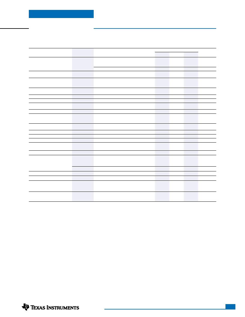
PT4822 Electrical Specifications
(Unless otherwise stated, the operating conditions are: T
a
=25°C, V
in
=48V, and I
o
=0.5I
o
max)
PT4822
Typ
Characteristics
Symbols
Conditions
Min
Max
Units
Output Current
I
o
Each output
Io
1
(3.3V)
Io
2
(1.8V)
Io
3
(1.5V)
0.25
(1)
0.1
0.1
—
36
—
3.24
1.76
1.47
—
—
—
—
—
—
—
—
—
—
—
—
—
—
350
—
—
—
—
—
—
—
—
—
3.3
1.8
1.5
±0.5
±0.5
±0.1
±0.1
—
—
86
40
25
25
200
3
±10
14
400
35.5
34
140
(4)
8
6
6
12
75
80
3.36
1.84
1.53
—
—
±0.5
±0.5
±3
(3)
±3
(3)
—
—
—
—
—
—
—
—
450
—
—
—
(2)
(2)
(2)
(1)
(1)
A
Total (Io
1
+ Io
2
+ Io
3
)
Continuous
Surge (1 minute)
(2)
A
Input Voltage Range
V
in
V
Set-Point Voltage
V
o
Vo
1
Vo
2
Vo
3
Vo
1
V
Temperature Variation
Reg
temp
–40°C
≤
T
a
≤
+85°C, I
o
=I
o
min
%V
o
Vo
2
/Vo
3
Line Regulation
Load Regulation
Total Output Voltage Variation
Reg
line
Reg
load
V
o
tol
All outputs, Over V
in
range
All outputs, 0
≤
I
o
≤
I
o
max
Includes set-point, line, load,
–40°C
≤
T
a
≤
+85°C
Io
1
=6A, Io
2
=2A, Io
3
=2A
%V
o
%V
o
Vo
1
%V
o
Vo
2
/Vo
3
Efficiency
V
Ripple/Noise
(0 to 20MHz bandwidth)
η
V
n
%
Vo
1
Vo
2
Vo
3
mV
pp
Transient Response
t
tr
V
os
V
o
adj
I
TRIP
s
V
on
V
off
t
on
0.1A/μs load step, 50% to 75% I
o
max
V
o
over/undershoot
μSec
%V
o
%V
o
A
kHz
V
Output Adjust Range
Over-Current Threshold
Switching Frequency
Under Voltage Lockout
Vo
1
/Vo
2
/Vo
3
Total, all outputs. Reset with auto-recovery
Over V
in
and I
o
ranges
V
in
increasing
V
in
decreasing
V
in
=48V step
Referenced to –V
in
(pin 4)
Turn-On Time
Enable Control (pins 1 & 2)
High-Level Input Voltage
Low-Level Input Voltage
Low-Level Input Current
Standby Input Current
Internal Input Capacitance
External Output Capacitance
ms
V
IH
V
IL
I
IL
I
in
standby
C
int
Co
1
Co
2
Co
3
V
iso
C
iso
R
iso
4
–0.2
—
—
—
0
0
0
1500
—
10
—
—
1
1
1.14
220
220
220
—
2,200
—
15
(5)
0.8
2
5
—
1,000
(6)
1,000
(6)
1,000
(6)
—
—
—
V
mA
mA
μF
pins 1 & 2 open circuit
μF
Primary/Secondary Isolation
V
pF
M
Notes:
(1) The converter will operate down to no load with reduced specifications.
(2) The sum-total current from outputs Vo
1
, Vo
2
, and Vo
3
cannot exceed 12ADC.
(3) Limits are specified by design.
(4) Measured from the application of the input voltage to the instance that all outputs are in regulation.
(5) The Enable inputs (pins 1 & 2) have internal pull-ups. Leaving pin 1 open-circuit and connecting pin 2 to –V
in
allows the the converter to operate when
input power is applied. The maximum open-circuit voltage is 4V.
(6) Ultra-low ESR capacitors, such as organic or polymer aluminum electrolytic types, may cause instability. Consult the factory before using.
相關PDF資料 |
PDF描述 |
|---|---|
| PT4832 | "5V/3.3V/2.5V 9A |
| PT4852 | "3.3V/1.8V/1.5V 25A |
| PT4853 | "3.3V/2.5V/1.2V 25A |
| PT4855 | "3.3V/1.5V/1.2V 25A |
| PT4856 | "5V/3.3V/1.5V |
相關代理商/技術參數 |
參數描述 |
|---|---|
| PT4827A | 功能描述:直流/直流開關轉換器 3.3/2.5/1.8V 12A 48V Inpt Iso DC/DC Cnvtr RoHS:否 制造商:STMicroelectronics 最大輸入電壓:4.5 V 開關頻率:1.5 MHz 輸出電壓:4.6 V 輸出電流:250 mA 輸出端數量:2 最大工作溫度:+ 85 C 安裝風格:SMD/SMT |
| PT4827C | 功能描述:直流/直流開關轉換器 3.3/2.5/1.8V 12A 48V Inpt Iso DC/DC Cnvtr RoHS:否 制造商:STMicroelectronics 最大輸入電壓:4.5 V 開關頻率:1.5 MHz 輸出電壓:4.6 V 輸出電流:250 mA 輸出端數量:2 最大工作溫度:+ 85 C 安裝風格:SMD/SMT |
| PT4827N | 功能描述:直流/直流開關轉換器 3.3/2.5/1.8V 12A 48V Inpt Iso DC/DC Cnvtr RoHS:否 制造商:STMicroelectronics 最大輸入電壓:4.5 V 開關頻率:1.5 MHz 輸出電壓:4.6 V 輸出電流:250 mA 輸出端數量:2 最大工作溫度:+ 85 C 安裝風格:SMD/SMT |
| PT4828 | 制造商:TI 制造商全稱:Texas Instruments 功能描述:35-W Triple Output Isolated DC/DC Converter for Logic Applications |
| PT4828A | 功能描述:直流/直流開關轉換器 5V/2.5V/1.5V 9A 48V Inpt Iso DC/DC Cnvtr RoHS:否 制造商:STMicroelectronics 最大輸入電壓:4.5 V 開關頻率:1.5 MHz 輸出電壓:4.6 V 輸出電流:250 mA 輸出端數量:2 最大工作溫度:+ 85 C 安裝風格:SMD/SMT |
發(fā)布緊急采購,3分鐘左右您將得到回復。