- 您現(xiàn)在的位置:買賣IC網(wǎng) > PDF目錄376251 > PSD313-15JI (意法半導(dǎo)體) Current-Mode PWM Controller 8-PDIP 0 to 70 PDF資料下載
參數(shù)資料
| 型號(hào): | PSD313-15JI |
| 廠商: | 意法半導(dǎo)體 |
| 英文描述: | Current-Mode PWM Controller 8-PDIP 0 to 70 |
| 中文描述: | 低成本現(xiàn)場(chǎng)可編程微控制器外圍設(shè)備 |
| 文件頁數(shù): | 27/85頁 |
| 文件大?。?/td> | 691K |
| 代理商: | PSD313-15JI |
第1頁第2頁第3頁第4頁第5頁第6頁第7頁第8頁第9頁第10頁第11頁第12頁第13頁第14頁第15頁第16頁第17頁第18頁第19頁第20頁第21頁第22頁第23頁第24頁第25頁第26頁當(dāng)前第27頁第28頁第29頁第30頁第31頁第32頁第33頁第34頁第35頁第36頁第37頁第38頁第39頁第40頁第41頁第42頁第43頁第44頁第45頁第46頁第47頁第48頁第49頁第50頁第51頁第52頁第53頁第54頁第55頁第56頁第57頁第58頁第59頁第60頁第61頁第62頁第63頁第64頁第65頁第66頁第67頁第68頁第69頁第70頁第71頁第72頁第73頁第74頁第75頁第76頁第77頁第78頁第79頁第80頁第81頁第82頁第83頁第84頁第85頁

PSD3XX Famly
24
12.0
Control Signals
(cont.)
12.6 Reset Input
This is an asynchronous input to initialize the PSD device.
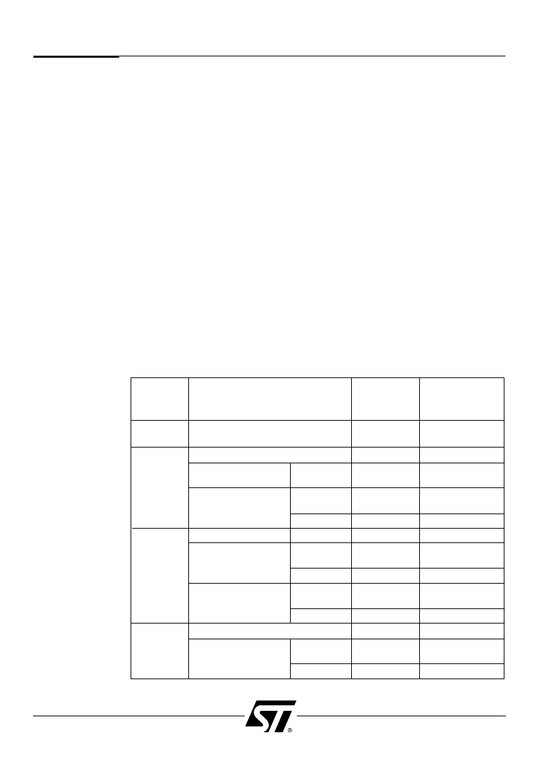
Refer to tables 8A and 8B for information on device status during and after reset.
The standard-voltage PSD3XX and ZPSD3XX (non-V) devices require a reset input that
is asserted for at least 100 nsec. The PSD will be functional immediately after reset is
de-asserted. For these standard-voltage devices, the polarity of the reset input signal is
programmable using PSDsoft (active-high or active-low), to match the functionality of your
MCU reset.
Note:
It is not recommended to drive the reset input of the MCU and the reset input of the
PSD with a simple RC circuit between power on ground. The input threshold of the MCU
and the PSD devices may differ, causing the devices to enter and exit reset at different
times because of slow ramping of the signal. This may result in the PSD not being
operational when accessed by the MCU. It is recommended to drive both devices actively.
A supervisory device or a gate with hysteresis is recommended.
For low-voltage ZPSD3XXV devices only, the reset input must be asserted for at least
500 nsec. The ZPSD3XXV will not be functional for an additional 500 nsec after reset is
de-asserted (see Figure 8). These low voltage ZPSD3XXV devices must use an active-low
polarity signal for reset. Unlike the standard PSDs, the reset polarity for the ZPSD3XXV is
not
programmable. If your MCU operates with an active high reset, you must invert this
signal before driving the ZPSD3XXV reset input.
You must design your system to ensure that the PSD comes out of reset and the PSD is
active before the MCU makes its first access to PSD memory. Depending on the
characteristics and speed of your MCU, a delay between the PSD reset and the MCU reset
may be needed.
Signal State Just
After Reset
(Note 1)
Signal State
During Reset
Port
Configured Mode of Operation
AD0/A0-
AD15/A15
All
Input (Hi-Z)
MCU address
and/or data
Input (Hi-Z)
Active Track
Mode
MCU I/O
Tracking
AD0/A0-AD7/A7
Input (Hi-Z)
Input (Hi-Z)
Port Pins
PA0-PA7
PSD3XX,
ZPSD3XX
ZPSD3XXV
Logic 0
MCU address
Latched Address Out
Hi-Z
MCU address
Input (Hi-Z)
MCU I/O
Input (Hi-Z
Chip Select Outputs,
CS0-CS7, CMOS
PSD3XX,
ZPSD3XX
ZPSD3XXV
PSD3XX,
ZPSD3XX
ZPSD3XXV
Logic 1
Per CS equations
Port Pins
PB0-PB7
Hi-Z
Per CS equations
Chip Select Outputs,
CS0-CS7, Open Drain
Hi-Z
Per CS equations
Hi-Z
Per CS equations
Input (Hi-Z)
Address or Logic Inputs, A16-A18
Input (Hi-Z)
Port Pins
PC0-PC2
Chip Select Outputs,
CS8-CS10, CMOS
PSD3XX,
ZPSD3XX
ZPSD3XXV
Logic 1
Per CS equations
Hi-Z
Per CS equations
Table 8A. External PSDSignal States During and Just After Reset
NOTE:
1. Signal is valid immediately after reset for PSD3XX and ZPSD3XX devices. ZPSD3XXV devices need an
additional 500 nsec after reset before signal is valid.
相關(guān)PDF資料 |
PDF描述 |
|---|---|
| PSD313-15JM | Low Cost Field Programmable Microcontroller Peripherals |
| PSD313-20J | Current Mode PWM Controller 14-SOIC 0 to 70 |
| PSD313-20JI | Current Mode PWM Controller 8-SOIC 0 to 70 |
| PSD313-20JM | Low Cost Field Programmable Microcontroller Peripherals |
| PSD313-25J | Current Mode PWM Controller 8-SOIC 0 to 70 |
相關(guān)代理商/技術(shù)參數(shù) |
參數(shù)描述 |
|---|---|
| PSD313-15JM | 制造商:STMICROELECTRONICS 制造商全稱:STMicroelectronics 功能描述:Low Cost Field Programmable Microcontroller Peripherals |
| PSD313-15LI | 制造商:未知廠家 制造商全稱:未知廠家 功能描述:Field-Programmable Peripheral |
| PSD313-15LM | 制造商:未知廠家 制造商全稱:未知廠家 功能描述:Field-Programmable Peripheral |
| PSD313-15Q | 制造商:未知廠家 制造商全稱:未知廠家 功能描述:Field-Programmable Peripheral |
| PSD313-15QI | 制造商:未知廠家 制造商全稱:未知廠家 功能描述:Field-Programmable Peripheral |
發(fā)布緊急采購,3分鐘左右您將得到回復(fù)。