- 您現(xiàn)在的位置:買(mǎi)賣(mài)IC網(wǎng) > PDF目錄69082 > PQ60015ETL45PKS-G (SYNQOR INC) 1-OUTPUT 67.5 W DC-DC REG PWR SUPPLY MODULE PDF資料下載
參數(shù)資料
| 型號(hào): | PQ60015ETL45PKS-G |
| 廠商: | SYNQOR INC |
| 元件分類(lèi): | 電源模塊 |
| 英文描述: | 1-OUTPUT 67.5 W DC-DC REG PWR SUPPLY MODULE |
| 封裝: | ROHS COMPLIANT, EIGHTH BRICK PACKAGE-8 |
| 文件頁(yè)數(shù): | 4/14頁(yè) |
| 文件大?。?/td> | 2155K |
| 代理商: | PQ60015ETL45PKS-G |
第1頁(yè)第2頁(yè)第3頁(yè)當(dāng)前第4頁(yè)第5頁(yè)第6頁(yè)第7頁(yè)第8頁(yè)第9頁(yè)第10頁(yè)第11頁(yè)第12頁(yè)第13頁(yè)第14頁(yè)
Product # PQ60015ETL45
Phone 1-888-567-9596
www.synqor.com
Doc.# 005-0005082 Rev. A
11/19/08
Page 12
Input:
Output:
Current:
Part no.:
35-75 V
1.5 V
45 A
PQ60015ETL45
Technical Specification
APPLICATION CONSIDERATIONS
Input System Instability: This condition can occur because
any DC/DC converter appears incrementally as a negative
resistance load. A detailed application note titled “Input
System Instability” is available on the SynQor website which
provides an understanding of why this instability arises, and
shows the preferred solution for correcting it.
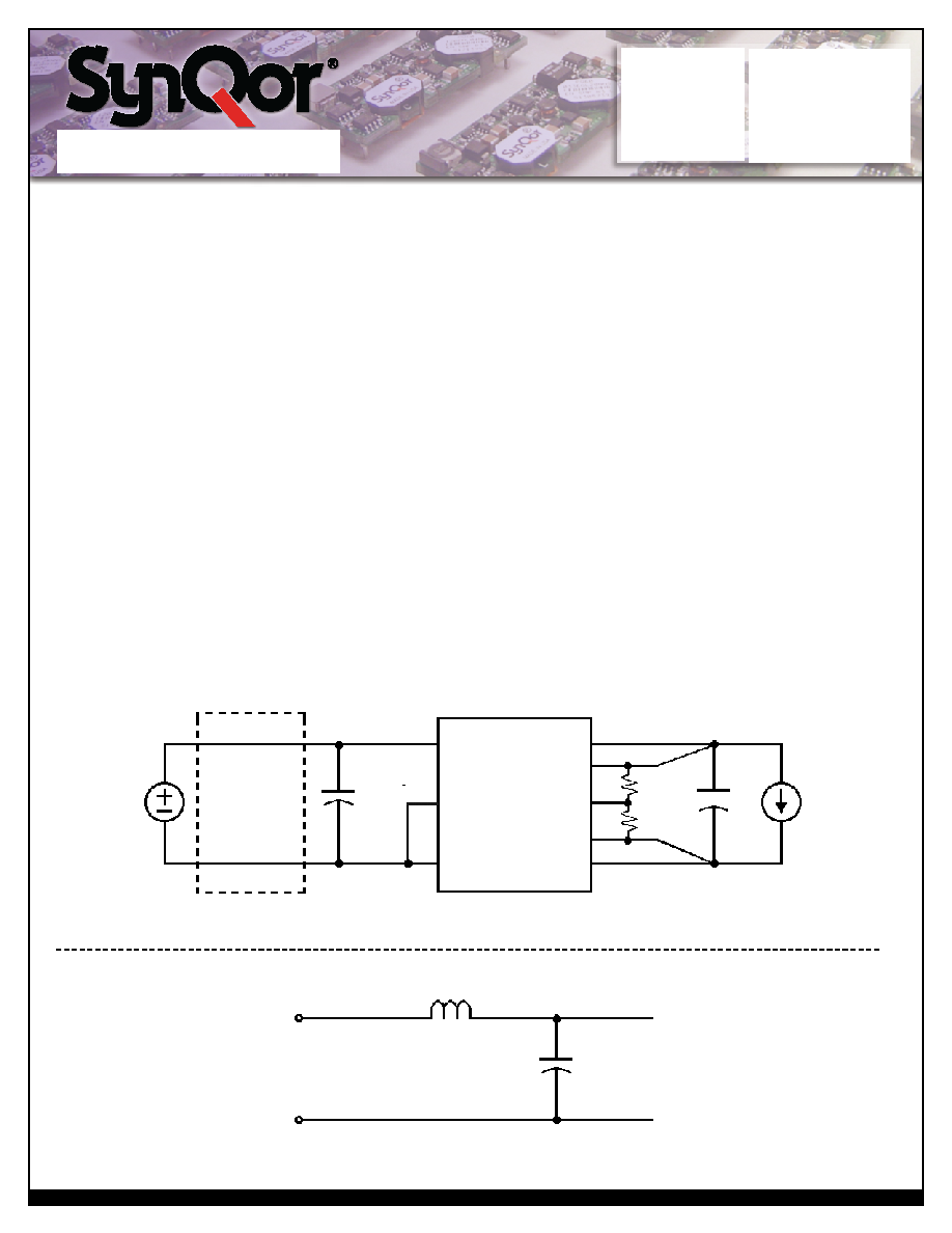
Application Circuits: Figure D below provides a typical circuit
diagram which details the input filtering and voltage trimming.
Input Filtering and External Capacitance: Figure E below
provides a diagram showing the internal input filter components.
This filter dramatically reduces input terminal ripple current,
which otherwise could exceed the rating of an external
input electrolytic capacitor. The recommended external input
capacitance is specified in the “Input Characteristics” section.
More detailed information is available in the application note
titled “EMI Characteristics” on the SynQor website.
Startup/Restart Inhibit Period: The Restart Inhibit Period
ensures that the converter will remain off for approximately
200ms once it is shut down. When an output short is present, this
generates a 5Hz “hiccup mode,” which prevents the converter
from overheating. In all, there are five ways that the converter
can be shut down that initiate a Restart Inhibit Period:
Input Under-Voltage Lockout
Output Over-Voltage Protection
Over Temperature Shutdown
Current Limit
Turned off by the ON/OFF input
Figure F shows four turn-on scenarios, where a Restart Inhibit
Period is initiated at t1, t2, and t3:
A Startup Inhibit Period is initiated when the input voltage is
brought up from zero voltage during initial startup, beginning as
the input voltage reaches approximately 10V. At the end of the
Startup Inhibit Period (typically 10mS), if the ON/OFF pin has
been active for at least 1ms, and the input voltage is above the
Under-Voltage Lockout threshold, the output turns on with the
Typical Turn-On Time. This is shown at time t0.
At time t1, the input voltage falls below the Input Under-Voltage
Lockout threshold. This disables the unit and initiates a Restart
Vin
External
Input
Filter
Trim
Vin(+)
Iload
Cload
L
C
Vout(+)
Rtrim-up
or
Rtrim-down
Vsense(+)
ON/OFF
Vin(_)
Vin(+)
Vin(_)
Vout(_)
Vsense(_)
Figure D: Typical application circuit (negative logic unit, permanently enabled).
Figure E: Internal Input Filter Diagram (component values listed on the specifications page).
Electrolytic
Capacitor
47F
相關(guān)PDF資料 |
PDF描述 |
|---|---|
| PQ60015ETL45NNS-G | 1-OUTPUT 67.5 W DC-DC REG PWR SUPPLY MODULE |
| PQ60015ETL45PRS-G | 1-OUTPUT 67.5 W DC-DC REG PWR SUPPLY MODULE |
| PQ60015HPAA0NNF-G | 1-OUTPUT 150 W DC-DC REG PWR SUPPLY MODULE |
| PQ60015HPAA0NRS-G | 1-OUTPUT 150 W DC-DC REG PWR SUPPLY MODULE |
| PQ60015HPAA0PNS-G | 1-OUTPUT 150 W DC-DC REG PWR SUPPLY MODULE |
相關(guān)代理商/技術(shù)參數(shù) |
參數(shù)描述 |
|---|---|
| PQ60015HPAA0 | 制造商:SYNQOR 制造商全稱(chēng):SYNQOR 功能描述:Half-brick DC/DC Converter |
| PQ60015HPAA0NKF-G | 制造商:SYNQOR 制造商全稱(chēng):SYNQOR 功能描述:Half-brick DC/DC Converter |
| PQ60015HPAA0NKS-G | 制造商:SYNQOR 制造商全稱(chēng):SYNQOR 功能描述:Half-brick DC/DC Converter |
| PQ60015HPAA0NNF-G | 制造商:SYNQOR 制造商全稱(chēng):SYNQOR 功能描述:Half-brick DC/DC Converter |
| PQ60015HPAA0NNS-G | 制造商:SYNQOR 制造商全稱(chēng):SYNQOR 功能描述:Half-brick DC/DC Converter |
發(fā)布緊急采購(gòu),3分鐘左右您將得到回復(fù)。