- 您現(xiàn)在的位置:買賣IC網(wǎng) > PDF目錄368095 > PPC405GP-3DE200CZ (APPLIEDMICRO INC) Power PC 405GP Embedded Processor PDF資料下載
參數(shù)資料
| 型號: | PPC405GP-3DE200CZ |
| 廠商: | APPLIEDMICRO INC |
| 元件分類: | 微控制器/微處理器 |
| 英文描述: | Power PC 405GP Embedded Processor |
| 中文描述: | 32-BIT, 200 MHz, RISC PROCESSOR, PBGA456 |
| 封裝: | 27 X 27 MM, PLASTIC, EBGA-456 |
| 文件頁數(shù): | 38/59頁 |
| 文件大小: | 782K |
| 代理商: | PPC405GP-3DE200CZ |
第1頁第2頁第3頁第4頁第5頁第6頁第7頁第8頁第9頁第10頁第11頁第12頁第13頁第14頁第15頁第16頁第17頁第18頁第19頁第20頁第21頁第22頁第23頁第24頁第25頁第26頁第27頁第28頁第29頁第30頁第31頁第32頁第33頁第34頁第35頁第36頁第37頁當(dāng)前第38頁第39頁第40頁第41頁第42頁第43頁第44頁第45頁第46頁第47頁第48頁第49頁第50頁第51頁第52頁第53頁第54頁第55頁第56頁第57頁第58頁第59頁
405GP – Power PC 405GP Embedded Processor
38
AMCC
Revision 2.03 – September 7, 2007
Data Sheet
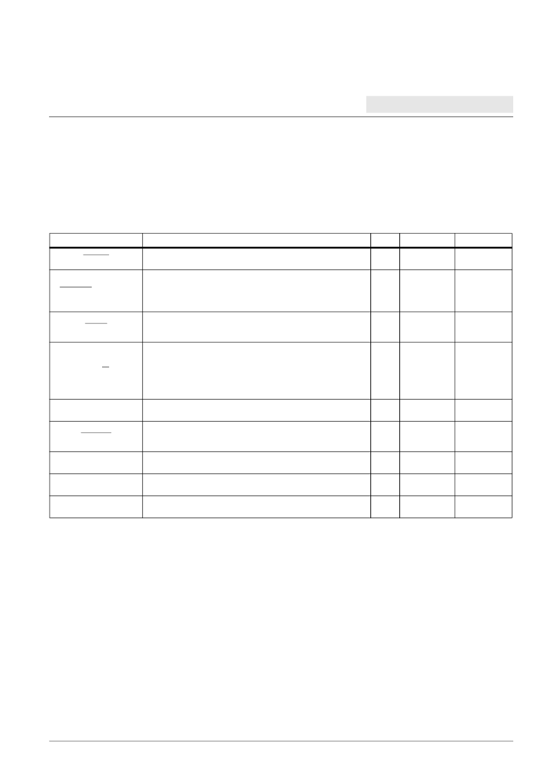
PerCS0
Peripheral chip select bank 0.
O
5V tolerant
3.3V LVTTL
7
PerCS1:7[GPIO10:16]
Seven additional peripheral chip selects
or
General Purpose I/O. To access this function, software must toggle a
DCR bit.
O[I/O]
5V tolerant
3.3V LVTTL
1, 7
PerOE
Used by either the peripheral controller or the DMA controller
depending upon the type of transfer involved. When the PPC405GP
is the bus master, it enables the selected device to drive the bus.
O
5V tolerant
3.3V LVTTL
7
PerR/W
Used by the PPC405GP when not in external master mode, as output
by either the peripheral controller or DMA controller depending upon
the type of transfer involved. High indicates a read from memory, low
indicates a write to memory.
Otherwise it used by the external master as an input to indicate the
direction of data transfer.
I/O
5V tolerant
3.3V LVTTL
1
PerReady
Used by a peripheral slave to indicate it is ready to transfer data.
I
5V tolerant
3.3V LVTTL
1
PerBLast
Used by the PPC405GP when not in external master mode,
otherwise used by external master. Indicates the last transfer of a
memory access.
I/O
5V tolerant
3.3V LVTTL
1, 7
DMAReq0:3
DMAReq0:3 are used by slave peripherals to indicate they are
prepared to transfer data.
I
5V tolerant
3.3V LVTTL
1
DMAAck0:3
DMAAck0:3 are used by the PPC405GP to cause the DMA
peripheral to transfer data.
O
5V tolerant
3.3V LVTTL
6
EOT0:3/TC0:3
End Of Transfer/Terminal Count.
I/O
5V tolerant
3.3V LVTTL
1
Signal Functional Description
(Part 4 of 8)
Multiplexed signals are shown in brackets following the first signal name assigned to each multiplexed ball.
Notes:
1. Receiver input has hysteresis.
2. Must pull up. See “Pull-Up and Pull-Down Resistors” on page 34 for recommended termination values.
3. Must pull down. See “Pull-Up and Pull-Down Resistors” on page 34 for recommended termination values.
4. If not used, must pull up.
5. If not used, must pull down.
6. Strapping input during reset; pull up or pull down as required.
7. Pull-up may be required. See “External Bus Control Signals” on page 34.
Signal Name
Description
I/O
Type
Notes
相關(guān)PDF資料 |
PDF描述 |
|---|---|
| PPC405GP-3DE266C | Power PC 405GP Embedded Processor |
| PPC405GP-3DE266CZ | Power PC 405GP Embedded Processor |
| PPC405GP-3EE200C | Power PC 405GP Embedded Processor |
| PPC405GP-3EE200CZ | Power PC 405GP Embedded Processor |
| PPC405GP-3EE266C | Power PC 405GP Embedded Processor |
相關(guān)代理商/技術(shù)參數(shù) |
參數(shù)描述 |
|---|---|
| PPC405GP-3DE266C | 制造商:AMCC 功能描述: 制造商:AppliedMicro 功能描述: |
| PPC405GP-3DE266CZ | 制造商:AppliedMicro 功能描述:MPU 405GP RISC 32-Bit 0.25um 266MHz 3.3V 456-Pin EBGA T/R |
| PPC405GP-3EE200C | 制造商:AMCC 制造商全稱:Applied Micro Circuits Corporation 功能描述:Power PC 405GP Embedded Processor |
| PPC405GP-3EE200CZ | 制造商:AMCC 制造商全稱:Applied Micro Circuits Corporation 功能描述:Power PC 405GP Embedded Processor |
| PPC405GP-3EE266C | 制造商:AppliedMicro 功能描述:MPU 405GP RISC 32-Bit 0.25um 266MHz 3.3V 413-Pin EBGA Tray |
發(fā)布緊急采購,3分鐘左右您將得到回復(fù)。