- 您現(xiàn)在的位置:買賣IC網(wǎng) > PDF目錄378058 > PMB8825 (INFINEON TECHNOLOGIES AG) Dual-Band Power Amplifier for WLAN Systems PDF資料下載
參數(shù)資料
| 型號: | PMB8825 |
| 廠商: | INFINEON TECHNOLOGIES AG |
| 英文描述: | Dual-Band Power Amplifier for WLAN Systems |
| 中文描述: | 雙頻功率放大器無線局域網(wǎng)系統(tǒng) |
| 文件頁數(shù): | 2/2頁 |
| 文件大?。?/td> | 188K |
| 代理商: | PMB8825 |

How to reach us:
http://www.infineon.com
Published by
Infineon Technologies AG,
St.-Martin-Strasse 53,
81669 München
Infineon Technologies AG 2003. All Rights Reserved.
Attention please!
The information herein is given to describe certain components
and shall not be considered as warranted characteristics.
Terms of delivery and rights to technical change reserved.
We hereby disclaim any and all warranties, including but not
limited to warranties of non-infringement, regarding circuits,
descriptions and charts stated herein.
Infineon Technologies is an approved CECC manufacturer.
Information
For further information on technology, delivery terms
and conditions and prices please contact your nearest
Infineon Technologies Office in Germany or our
Infineon Technologies Representatives worldwide.
Warnings
Due to technical requirements components may contain dan-
gerous substances. For information on the types in question
please contact your nearest Infineon Technologies Office.
Infineon Technologies Components may only be used in life-
support devices or systems with the express written approval
of Infineon Technologies, if a failure of such components can
reasonably be expected to cause the failure of that life-support
device or system, or to affect the safety or effectiveness of that
device or system. Life-support devices or systems are intend-
ed to be implanted in the human body, or to support and/or
maintain and sustain and/or protect human life. If they fail, it is
reasonable to assume that the health of the user or other
persons may be endangered.
Published by Infineon Technologies AG
P
R O D U C T
B
R I E F
Type
WLAN Power Amplifier
Sales Code
PMB 8825
Package
P-VQFN-24
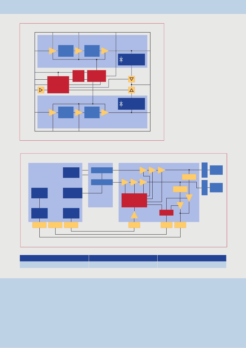
Block Diagram
Analog Power
Control
Standby
Band
Gap
Band Select
Biasing
1
st
Driver
Stage
Diode + Temp.
Compensation
Interstage
Matching
Interstage
Matching
5 GHz
2
nd
Driver
Stage
Output
Stage
1
st
Driver
Stage
Diode + Temp.
Compensation
Interstage
Matching
Interstage
Matching
2 GHz
2
nd
Driver
Stage
Output
Stage
RF
Output
5 GHz
RF
Output
2 GHz
Power
Detect
V
CC2
V
CC1
V
CC5
V
CC6
BREF
RF
Input
5 GHz
Power
Control
Band
Select
Enable
V
CC
RF
Input
2 GHz
Frequency Bands
■
2.4 GHz ... 2.5 GHz Band
- P
sat
= 30 dB
- P
1dB
= 27 dBm
- Gain = 31 dB
■
5.15 GHz ... 5.825 GHz Band
- P
sat
= 27 dBm
- P
1dB
= 24 dBm
- Gain = 22 dB
Biasing
Logic
OP
OP
Diode
Diode
OP
PMB 8825
RF
5 GHz PGC
2 GHz PGC
PMB 8680
Mixed
Signal
Bus
PMB 8787
BB-PHY IC
DAC
ADC
HW + SW
RF-Transceiver IC
PA_PDT
PA_ON
PA_ON
PC
PAON
PDT
M
50
Fronted
50
Fronted
M
Analog power control with a 10 dB dynamic range to optimize efficiency at all power levels.
Example: Power Control Loop for WLAN System (simplified)
Printed in Germany
PS 03031.
NB
相關(guān)PDF資料 |
PDF描述 |
|---|---|
| PMB8875 | S-GOLDlite- Advanced Single - Chip GSM/GPRS Baseband Controller |
| PMB8876 | S-GOLD2⑩-Multimedia Engine with Advanced EDGE Modem Functionality |
| PMB9500 | 3G Basestation Pro cessor |
| PMC520 | PMC520 Octal Serial 232 Communication |
| PMC520-64 | PMC520 Octal Serial 232 Communication |
相關(guān)代理商/技術(shù)參數(shù) |
參數(shù)描述 |
|---|---|
| PMB8870 | 制造商:INFINEON 制造商全稱:Infineon Technologies AG 功能描述:single chip baseband IC |
| PMB8870V1.1 | 制造商:Infineon Technologies AG 功能描述: |
| PMB8875 | 制造商:INFINEON 制造商全稱:Infineon Technologies AG 功能描述:S-GOLDlite- Advanced Single - Chip GSM/GPRS Baseband Controller |
| PMB8876 | 制造商:INFINEON 制造商全稱:Infineon Technologies AG 功能描述:S-GOLD2⑩-Multimedia Engine with Advanced EDGE Modem Functionality |
| PMB8877 | 制造商:INFINEON 制造商全稱:Infineon Technologies AG 功能描述:S-GOLD3 - Turbo Enginefor |
發(fā)布緊急采購,3分鐘左右您將得到回復(fù)。