- 您現(xiàn)在的位置:買賣IC網(wǎng) > PDF目錄369996 > PG001 (Allegro MicroSystems, Inc.) PARALLEL-TO-SERIAL DATA CONVERTER PDF資料下載
參數(shù)資料
| 型號: | PG001 |
| 廠商: | Allegro MicroSystems, Inc. |
| 英文描述: | PARALLEL-TO-SERIAL DATA CONVERTER |
| 中文描述: | 并行到串行數(shù)據(jù)轉(zhuǎn)換器 |
| 文件頁數(shù): | 7/12頁 |
| 文件大小: | 179K |
| 代理商: | PG001 |

PG001M
PARALLEL-TO-SERIAL
DATA CONVERTER
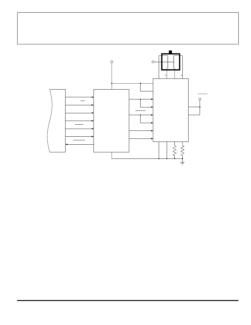
Figure 3 — Typical 'Integrated' Microstepping System
REF/ENABLE
CLOCK
STROBE
SERIAL DATA
SERIAL DATA
Dwg. EK-014A
1
MODE SELECT
MONITOR
CCW/CW
RESET
VECTOR CONTROL
MODE SELECT2
μ
P
CLOCKIN
S
o
S
RS
RS
GB
GA
P
GND
A
A
B
B
VDD
A
A
B
A
B
A
B
OUT
VBB
CONTROL SUPPLY
B
+5 V
A
B
After the RESET pulse, the first (two) full-steps in the
microstepping sequence, MS
1
is switched LOW and the
control IC shifts into the 1/4-step mode. It becomes very
apparent that any microstepping directly from a
μ
P to the
SLA7042/44M module 'burdens' the
μ
P, complicates the
software, and might entail a 'dedicated' microcontroller in
many motion-control systems.
The PG001M controller IC precludes loading a
μ
P
with direct serial-data signals to the power multi-chip
module. Because the step motor is updated at eight times
the step rate, this CMOS IC both simplifies software and
eliminates loading a system microprocessor with 'house-
keeping' control of step motors.
As illustrated in figures 4 and 5, the controller IC
eliminates the requirement to program the system for the
various modes of operation and the continual updating of
the serial-data signals to the power multi-chip module.
NOTE — In figures 4 and 5, the clock frequency is
constant during the few steps of operation that are shown
and half-step operation is not included.
Depicted in figure 4 are the 'front-end' I/O signals
(from RESET to VECTOR CONTROL), converted signals
from the controller IC to the microstepping power module
(CLOCK
OUT
, SERIAL DATA
A
, SERIAL DATA
B
, and
STROBE), plus the MONITOR (readback) to the
microcontroller. Finally, the power multi-chip module
current ratios are illustrated (OUT
A
and OUT
B
).
As shown, initially the counter is reset, and then the
motor is operating in quarter-step mode; then MS
2
is
switched while MO is LOW. The two steps following are
full-step (100% torque vector). The final (fourth quadrant)
portion of figure 4 is the maximum (141%) torque mode,
after VECTOR CONTROL has been switched from LOW
to HIGH. Three of the five operational modes are shown,
and none require the
μ
P to continually update the clock,
serial-data input, or strobe to the SLA7042/44M module.
The microstepping operation is illustrated in figure 5.
Initially the counter is reset, and with both MODE SE-
LECTs HIGH the controller is furnishing clock, serial
data, and strobe logic signals for 1/8
th
step increments.
相關PDF資料 |
PDF描述 |
|---|---|
| PG001 | Serial Signal Generator IC for SLA7042M and SLA7044M |
| PG001M | Serial Signal Generator IC for SLA7042M and SLA7044M |
| PG001M | PARALLEL-TO-SERIAL DATA CONVERTER |
| PG1113F | 1113F Series, Right Angle SMT LED |
| PG1157 | TRANSISTOR | BJT | NPN | 60V V(BR)CEO | 5A I(C) | TO-5 |
相關代理商/技術參數(shù) |
參數(shù)描述 |
|---|---|
| PG0015.103NLT | 功能描述:固定電感器 IND RoHS:否 制造商:AVX 電感:10 uH 容差:20 % 最大直流電流:1 A 最大直流電阻:0.075 Ohms 工作溫度范圍:- 40 C to + 85 C 自諧振頻率:38 MHz Q 最小值:40 尺寸:4.45 mm W x 6.6 mm L x 2.92 mm H 屏蔽:Shielded 端接類型:SMD/SMT 封裝 / 箱體:6.6 mm x 4.45 mm |
| PG0015.104NLT | 功能描述:固定電感器 IND RoHS:否 制造商:AVX 電感:10 uH 容差:20 % 最大直流電流:1 A 最大直流電阻:0.075 Ohms 工作溫度范圍:- 40 C to + 85 C 自諧振頻率:38 MHz Q 最小值:40 尺寸:4.45 mm W x 6.6 mm L x 2.92 mm H 屏蔽:Shielded 端接類型:SMD/SMT 封裝 / 箱體:6.6 mm x 4.45 mm |
| PG0015.123NLT | 功能描述:固定電感器 IND RoHS:否 制造商:AVX 電感:10 uH 容差:20 % 最大直流電流:1 A 最大直流電阻:0.075 Ohms 工作溫度范圍:- 40 C to + 85 C 自諧振頻率:38 MHz Q 最小值:40 尺寸:4.45 mm W x 6.6 mm L x 2.92 mm H 屏蔽:Shielded 端接類型:SMD/SMT 封裝 / 箱體:6.6 mm x 4.45 mm |
| PG0015.124NLT | 功能描述:固定電感器 IND RoHS:否 制造商:AVX 電感:10 uH 容差:20 % 最大直流電流:1 A 最大直流電阻:0.075 Ohms 工作溫度范圍:- 40 C to + 85 C 自諧振頻率:38 MHz Q 最小值:40 尺寸:4.45 mm W x 6.6 mm L x 2.92 mm H 屏蔽:Shielded 端接類型:SMD/SMT 封裝 / 箱體:6.6 mm x 4.45 mm |
| PG0015.152NLT | 制造商:Pulse Electronics Corporation 功能描述:Ind Power Unshielded Wirewound 1.5uH 20% 11A T/R 制造商:Pulse Electronics Corporation 功能描述:Inductor Power Unshielded Wirewound 1.5uH 20% 11A 8mOhm DCR T/R |
發(fā)布緊急采購,3分鐘左右您將得到回復。