- 您現(xiàn)在的位置:買賣IC網(wǎng) > PDF目錄385712 > PF5001 (Won-Top Electronics Co., Ltd.) 50A 1/2 PRESS-FIT DIODE PDF資料下載
參數(shù)資料
| 型號: | PF5001 |
| 廠商: | Won-Top Electronics Co., Ltd. |
| 英文描述: | 50A 1/2 PRESS-FIT DIODE |
| 中文描述: | 50A條1 / 2壓接二極管 |
| 文件頁數(shù): | 1/2頁 |
| 文件大小: | 23K |
| 代理商: | PF5001 |
PF5000 – PF5010
1 of 2 2002 Won-Top Electronics
PF5000 – PF5010
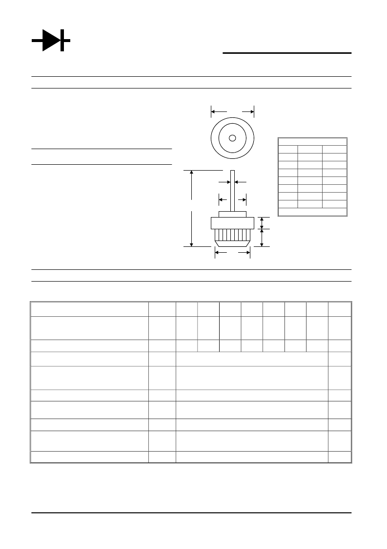
50A 1/2" PRESS-FIT DIODE
Features
!
Diffused Junction
!
Low Leakage
!
Low Cost A
!
High Surge Current Capability
!
Typical I
R
less than 10μA
Mechanical Data
!
Case: All Copper Case and Components
Hermetically Sealed D
Terminals: Contact Areas Readily Solderable
Polarity: Cathode to Case(Reverse Units Are C
Available Upon Request and Are Designated G
By An “R” Suffix, i.e. PF5002R or PF5010R)
Polarity: Red Color Equals Standard, E
Black Color Equals Reverse Polarity
Mounting Position: Any F
B
!
!
!
!
Maximum Ratings and Electrical Characteristics
@T
A
=25°C unless otherwise specified
Single Phase, half wave, 60Hz, resistive or inductive load.
For capacitive load, derate current by 20%.
Characteristic
Symbol
PF5000 PF5001 PF5002 PF5004 PF5006 PF5008 PF5010
Unit
Peak Repetitive Reverse Voltage
Working Peak Reverse Voltage
DC Blocking Voltage
V
RRM
V
RWM
V
R
50
100
200
400
600
800
1000
V
RMS Reverse Voltage
V
R(RMS)
35
70
140
280
420
560
700
V
Average Rectified Output Current @T
A
= 150°C
I
O
50
A
Non-Repetitive Peak Forward Surge Current
8.3ms Single half sine-wave superimposed on
rated load (JEDEC Method)
I
FSM
500
A
Forward Voltage @I
F
= 100A
V
FM
1.08
V
Peak Reverse Current @T
= 25°C
At Rated DC Blocking Voltage @T
A
= 100°C
I
RM
10
500
μA
Typical Junction Capacitance (Note 1)
C
j
300
pF
Typical Thermal Resistance Junction to Case
(Note 2)
R
JC
1.2
K/W
Operating and Storage Temperature Range
T
J
, T
STG
-65 to +175
°C
*Glass passivated forms are available upon request
Note: 1. Measured at 1.0 MHz and applied reverse voltage of 4.0V D.C.
2. Thermal Resistance: Junction to case, single side cooled.
W TE
POWER SEMICONDUCTORS
DO-21
Min
15.63
12.75
8.89
1.25
3.05
5.59
28.82
Dim
A
B
C
D
E
F
G
All Dimensions in mm
Max
16.14
12.83
10.04
1.30
3.30
6.1
—
相關PDF資料 |
PDF描述 |
|---|---|
| PFC-A1 | GENERAL PURPOSE RELAY |
| PFP-100N | GENERAL PURPOSE RELAY |
| PFP-50N | GENERAL PURPOSE RELAY |
| PFP-M | GENERAL PURPOSE RELAY |
| PFR 850SXX | Fast Recovery Rectifier Diodes(快速修復整流二極管) |
相關代理商/技術參數(shù) |
參數(shù)描述 |
|---|---|
| PF5002 | 制造商:WTE 制造商全稱:Won-Top Electronics 功能描述:50A 1/2 PRESS-FIT DIODE |
| PF5003 | 制造商:WTE 制造商全稱:Won-Top Electronics 功能描述:50A 1/2 PRESS-FIT DIODE |
| PF500-360 | 制造商:TDK-Lambda Corporation 功能描述:500W Power Module - 85-265V/170-265V in - 360V 1.4A, 360V 2.1A out |
| PF5004 | 制造商:WTE 制造商全稱:Won-Top Electronics 功能描述:50A 1/2 PRESS-FIT DIODE |
| PF5005 | 制造商:WTE 制造商全稱:Won-Top Electronics 功能描述:50A 1/2 PRESS-FIT DIODE |
發(fā)布緊急采購,3分鐘左右您將得到回復。