- 您現(xiàn)在的位置:買(mǎi)賣(mài)IC網(wǎng) > PDF目錄385707 > PD784054GCA2 (NEC Corp.) 16-BIT SINGLE-CHIP MICROCONTROLLER PDF資料下載
參數(shù)資料
| 型號(hào): | PD784054GCA2 |
| 廠(chǎng)商: | NEC Corp. |
| 英文描述: | 16-BIT SINGLE-CHIP MICROCONTROLLER |
| 中文描述: | 16位單片機(jī) |
| 文件頁(yè)數(shù): | 45/86頁(yè) |
| 文件大?。?/td> | 579K |
| 代理商: | PD784054GCA2 |
第1頁(yè)第2頁(yè)第3頁(yè)第4頁(yè)第5頁(yè)第6頁(yè)第7頁(yè)第8頁(yè)第9頁(yè)第10頁(yè)第11頁(yè)第12頁(yè)第13頁(yè)第14頁(yè)第15頁(yè)第16頁(yè)第17頁(yè)第18頁(yè)第19頁(yè)第20頁(yè)第21頁(yè)第22頁(yè)第23頁(yè)第24頁(yè)第25頁(yè)第26頁(yè)第27頁(yè)第28頁(yè)第29頁(yè)第30頁(yè)第31頁(yè)第32頁(yè)第33頁(yè)第34頁(yè)第35頁(yè)第36頁(yè)第37頁(yè)第38頁(yè)第39頁(yè)第40頁(yè)第41頁(yè)第42頁(yè)第43頁(yè)第44頁(yè)當(dāng)前第45頁(yè)第46頁(yè)第47頁(yè)第48頁(yè)第49頁(yè)第50頁(yè)第51頁(yè)第52頁(yè)第53頁(yè)第54頁(yè)第55頁(yè)第56頁(yè)第57頁(yè)第58頁(yè)第59頁(yè)第60頁(yè)第61頁(yè)第62頁(yè)第63頁(yè)第64頁(yè)第65頁(yè)第66頁(yè)第67頁(yè)第68頁(yè)第69頁(yè)第70頁(yè)第71頁(yè)第72頁(yè)第73頁(yè)第74頁(yè)第75頁(yè)第76頁(yè)第77頁(yè)第78頁(yè)第79頁(yè)第80頁(yè)第81頁(yè)第82頁(yè)第83頁(yè)第84頁(yè)第85頁(yè)第86頁(yè)
μ
PD784054(A)
45
9.1 Memory Expansion
The external program memory or data memory can be expanded from 256 bytes up to 1M bytes in seven
steps.
When an external device is connected, the address/data bus and read/write strobe signals are controlled by
using ports 4 through 6 and P90 through P93 pins. The functions of these ports and pins are set by the memory
expansion mode register (MM).
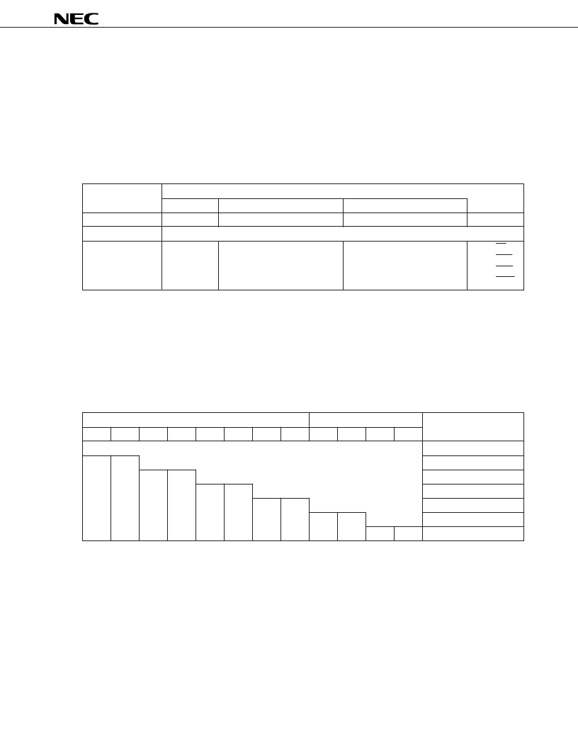
Table 9-1. Setting of Pin Function
Memory Expansion
Pin Function
Mode Register
Port 4
Port 5
Port 6
MM0-MM3
P40-P47
P50-P57
P60-P63
P90-P93
Port mode
General-purpose port
External memory
expansion mode
AD0-AD7
AD8 to AD15 are set stepwise.
Rest of pins can be used as
general-purpose port pins.
A16 through A19 are set
stepwise.
Rest of pins can be used as
general-purpose port pins.
P90 : RD
P91 : LWR
P92 : HWR
P93 : ASTB
Remark
AD8 through AD15 are used as address bus.
The number of pins of ports 5 and 6 that are used as address bus pins can be changed according to the size
of the external memory connected (external address space), so that the external memory can be expanded
stepwise. The pins not used as address bus pins can be used as general-purpose I/O port pins (refer to
Table
9-2
). The external address space can be set in seven steps by MM.
Table 9-2. Operations of Ports 5 and 6 (in external memory expansion mode)
Port 5
Port 6
External address space
P50
P51
P52
P53
P54
P55
P56
P57
P60
P61
P62
P63
General-purpose port
256 bytes or less
Note
AD8
AD9
1K bytes or less
Note
AD10
AD11
4K bytes or less
Note
AD12
AD13
16K bytes or less
Note
AD14
AD15
64K bytes or less
A16
A17
256K bytes or less
A18
A19
1M bytes or less
Note
When the external 16-bit bus is specified, do not set MM such that the external address space is of this size.
Caution
When the external 16-bit bus is specified, set MM such that all the pins of port 5 (P50 through P57)
are used as AD pins (AD8 through AD15).
相關(guān)PDF資料 |
PDF描述 |
|---|---|
| PD784976A | 16-Bit Single-Chip Microcontroller |
| PDA17-VS20-102AK | 17 mm Rotary Potentiometer |
| PDA17-AN25-102AF | 17 mm Rotary Potentiometer |
| PDA17-AN25-102AK | 17 mm Rotary Potentiometer |
| PDA17-AN25-102BF | 17 mm Rotary Potentiometer |
相關(guān)代理商/技術(shù)參數(shù) |
參數(shù)描述 |
|---|---|
| PD784976A | 制造商:NEC 制造商全稱(chēng):NEC 功能描述:16-Bit Single-Chip Microcontroller |
| PD7869 | 制造商:未知廠(chǎng)家 制造商全稱(chēng):未知廠(chǎng)家 功能描述:Optoelectronic |
| PD78F0134 | 制造商:NEC 制造商全稱(chēng):NEC 功能描述:8-Bit Single-Chip Microcontrollers |
| PD78F0134(A) | 制造商:NEC 制造商全稱(chēng):NEC 功能描述:8-Bit Single-Chip Microcontrollers |
| PD78F0134(A1) | 制造商:NEC 制造商全稱(chēng):NEC 功能描述:8-Bit Single-Chip Microcontrollers |
發(fā)布緊急采購(gòu),3分鐘左右您將得到回復(fù)。