- 您現(xiàn)在的位置:買賣IC網 > PDF目錄378041 > PBL388141N (ERICSSON) Voice - switched 2-channel Circuit with loudspeaker amplifier PDF資料下載
參數資料
| 型號: | PBL388141N |
| 廠商: | ERICSSON |
| 英文描述: | Voice - switched 2-channel Circuit with loudspeaker amplifier |
| 中文描述: | 語音-開關2聲道揚聲器放大器電路 |
| 文件頁數: | 6/14頁 |
| 文件大小: | 239K |
| 代理商: | PBL388141N |
6
PBL 388 14
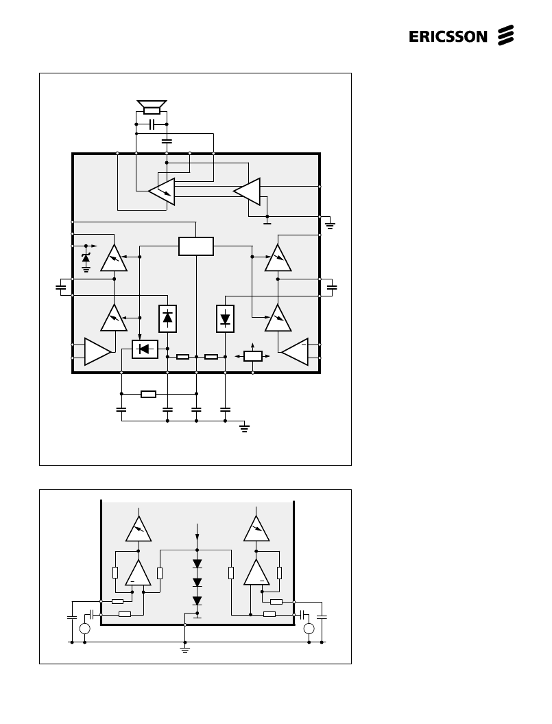
Figure 6. Receive and transmit channel input arrangement.
Figure 5. Passive networks setting the speech control function.
R5
C3
C1
C2
C4
F
2
F
3
F
1
+
PBL 388 14
20
24
4
16
21
3
1
2
8
6
9
10
23
17
18
19
22
+
-
CTR
CMP
GND
V
+
N
Det
R
xout
xin
+
R
xin
T
xDet
R
xDet
LSP
in
-T
xin
+
T
xin
T
xout
-R
11
14
15
F
6
F
5
Control
F
4
+
LSP
V
A
Ref.
VOL
13
11
5
+
+
+
GND
A
LL
7
+
F
1
F
4
1
2
14
15
F
5
+
+
F
2
V
Rxin
V
Txin
100k
3k
100k
120k
120k
20k
Tx
Ref.
I
~
17
3k
20k
PBL388 14
~
Rx
Functional Description
Speech control section
Transmitter and Receiver
Channels
The transmitter and receiver channels
consist of three amplifying stages each, F1,
F2, F3 and F4, F5, F6. The inputs of the
amplifiers must be ac. coupled because
they are dc. vise at the internal reference
voltage (
≈
2V) level. F1 and F4 are fixed
gain amplifiers of 29.5 dB and 15.5 dB
respectively, while the rest of them are of
controlled gain type amplifiers.The gain of
F2, F3 as well as F5 and F6 is controlled by
the comparator. Ac. loading the channel
outputs F3 and F6 will lessen the dc.
current consumption, maximum load 10
k
. The output capacity can be increased
somewhat in case needed, by coupling a
10 k
resistor from the respective output
pin directly to ground (before the optional
capacitor).The comparator receives its in-
formation from the summing point of the
transmitter, receiver and background noise
detectors at CMP input. The control input
CTR, controls the gain dynamics (25 or 50
dB). Amplifiers F2 and F3 have the maxi-
mum gain when the transmitter channel is
fully open, consequently the amplifiers F5
and F6 will have minimum gain and vice
versa. See figure 5 and figure 11.
The positive input on each channel
has a high input impedance. It renders a
good gain precision and noise performance
when used with low impedance signal
source . The negative input of the receiver
channel should be returned to ground with
a capacitor. The differential input of the
transmitter channel can be used to sup-
press unwanted signals in the microphone
supply, see figure 7. Also see application.
Signal Detectors and the
Comparator
The signal detectors sense and rectify
the receiver and microphone signals to
opposite polarities referenced to the internal
reference voltage of approx. 2V. The voltage
at RxDet will go positive and at TxDet
negative in the presence of a signal at the
respective channel input. In the idle (no
signal) state, the voltages at RxDet ,TxDet
and CMP are equal to the internal reference
voltage. Signal at Txin will result in a
decreasing level at TxDetout and hence
also at CMP input.
相關PDF資料 |
PDF描述 |
|---|---|
| PBL388141SO | Voice - switched 2-channel Circuit with loudspeaker amplifier |
| PBL388141SOT | Voice - switched 2-channel Circuit with loudspeaker amplifier |
| PBL40215 | RF Transceiver circuit for the Digital Enhanced Cordless Telecommunications (DECT) system |
| PBL40305 | Multiband GSM Power Amplifier |
| PBL40307 | GSM Dual Band Tx_VCO |
相關代理商/技術參數 |
參數描述 |
|---|---|
| PBL388141SO | 制造商:ERICSSON 制造商全稱:Ericsson 功能描述:Voice - switched 2-channel Circuit with loudspeaker amplifier |
| PBL388141SOT | 制造商:ERICSSON 制造商全稱:Ericsson 功能描述:Voice - switched 2-channel Circuit with loudspeaker amplifier |
| PBL3-RP15 | 制造商:Middle Atlantic Products 功能描述: |
| PBL4 | 制造商:Brady Corporation 功能描述: |
| PBL-4 | 制造商:Middle Atlantic Products 功能描述: |
發(fā)布緊急采購,3分鐘左右您將得到回復。