- 您現(xiàn)在的位置:買賣IC網(wǎng) > PDF目錄224672 > PALCE22V10H-15PI/4 (LATTICE SEMICONDUCTOR CORP) 24-Pin EE CMOS (Zero Power) Versatile PAL Device PDF資料下載
參數(shù)資料
| 型號: | PALCE22V10H-15PI/4 |
| 廠商: | LATTICE SEMICONDUCTOR CORP |
| 元件分類: | PLD |
| 英文描述: | 24-Pin EE CMOS (Zero Power) Versatile PAL Device |
| 中文描述: | EE PLD, 15 ns, PDIP24 |
| 封裝: | 0.300 INCH, SKINNY, PLASTIC, DIP-24 |
| 文件頁數(shù): | 12/34頁 |
| 文件大?。?/td> | 691K |
| 代理商: | PALCE22V10H-15PI/4 |
第1頁第2頁第3頁第4頁第5頁第6頁第7頁第8頁第9頁第10頁第11頁當(dāng)前第12頁第13頁第14頁第15頁第16頁第17頁第18頁第19頁第20頁第21頁第22頁第23頁第24頁第25頁第26頁第27頁第28頁第29頁第30頁第31頁第32頁第33頁第34頁
2
PALCE22V10 and PALCE22V10Z Families
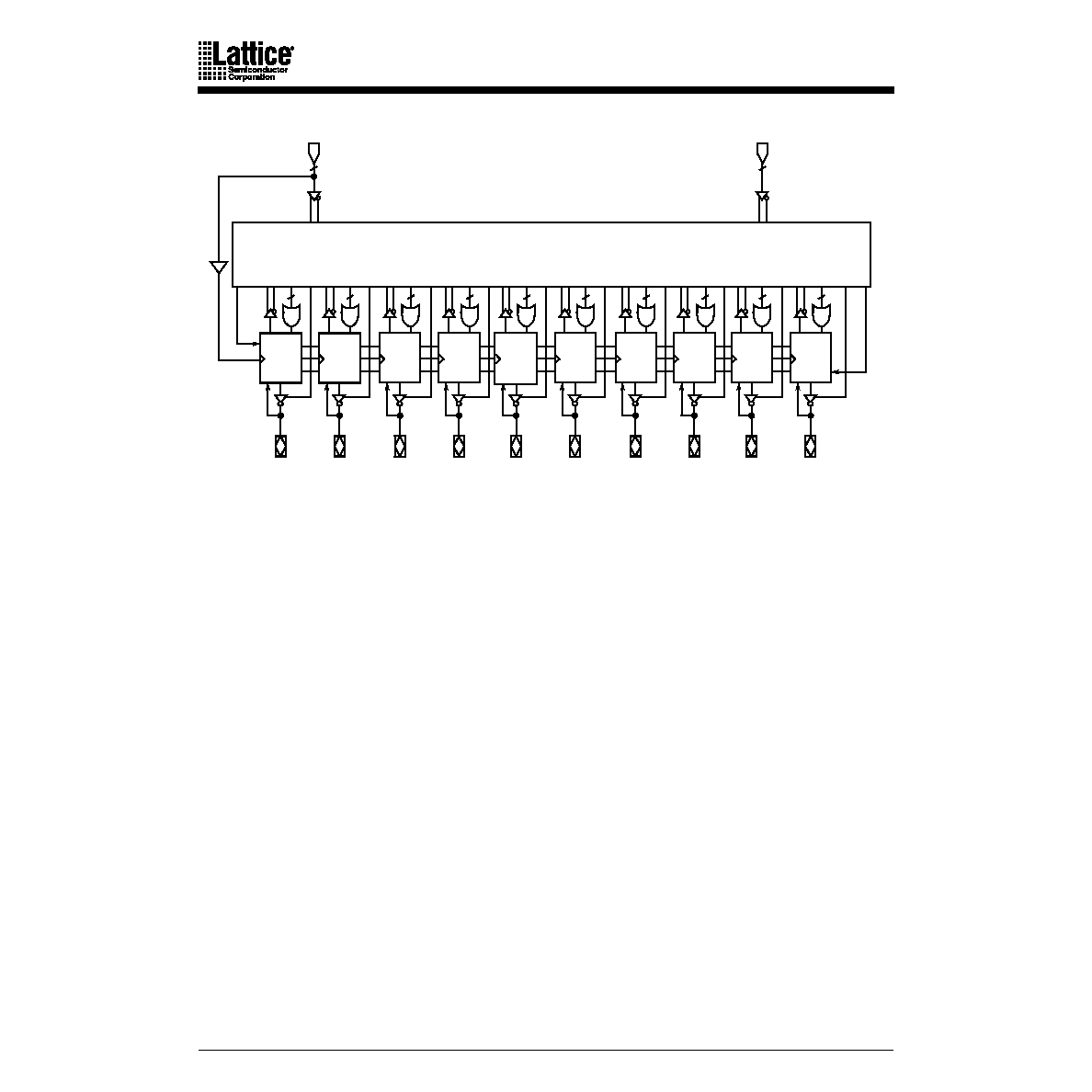
BLOCK DIAGRAM
FUNCTIONAL DESCRIPTION
The PALCE22V10 allows the systems engineer to implement the design on-chip, by programming
EE cells to congure AND and OR gates within the device, according to the desired logic function.
Complex interconnections between gates, which previously required time-consuming layout, are
lifted from the PC board and placed on silicon, where they can be easily modied during
prototyping or production.
The PALCE22V10Z is the zero-power version of the PALCE22V10. It has all the architectural features
of the PALCE22V10. In addition, the PALCE22V10Z has zero standby power and unused product
term disable.
Product terms with all connections opened assume the logical HIGH state; product terms
connected to both true and complement of any single input assume the logical LOW state.
The PALCE22V10 has 12 inputs and 10 I/O macrocells. The macrocell (Figure 1) allows one of four
potential output congurations registered output or combinatorial I/O, active high or active low
(see Figure 1). The conguration choice is made according to the user’s design specication and
corresponding programming of the conguration bits S0 - S1. Multiplexer controls are connected
to ground (0) through a programmable bit, selecting the “0” path through the multiplexer. Erasing
the bit disconnects the control line from GND and it is driven to a high level, selecting the “1” path.
The device is produced with an EE cell link at each input to the AND gate array, and connections
may be selectively removed by applying appropriate voltages to the circuit. Utilizing an easily-
implemented programming algorithm, these products can be rapidly programmed to any
customized pattern.
OUTPUT
LOGIC
MACRO
CELL
OUTPUT
LOGIC
MACRO
CELL
OUTPUT
LOGIC
MACRO
CELL
OUTPUT
LOGIC
MACRO
CELL
OUTPUT
LOGIC
MACRO
CELL
OUTPUT
LOGIC
MACRO
CELL
OUTPUT
LOGIC
MACRO
CELL
OUTPUT
LOGIC
MACRO
CELL
OUTPUT
LOGIC
MACRO
CELL
OUTPUT
LOGIC
MACRO
CELL
RESET
PRESET
CLK/I0
1
I1 - I11
11
8
1012
14
16
1614
12
10
8
I/O0
I/O1
I/O2
I/O3
I/O4
I/O5
I/O6
I/O7
I/O8
I/O9
PROGRAMMABLE
AND ARRAY
(44 x 132)
相關(guān)PDF資料 |
PDF描述 |
|---|---|
| PALCE22V10H-20PI/4 | 24-Pin EE CMOS (Zero Power) Versatile PAL Device |
| PALCE22V10H-25PI/4 | 24-Pin EE CMOS (Zero Power) Versatile PAL Device |
| PALCE22V10H-15JC/4 | 24-Pin EE CMOS (Zero Power) Versatile PAL Device |
| PALCE22V10H-25JC/4 | 24-Pin EE CMOS (Zero Power) Versatile PAL Device |
| PALCE22V10H-5JC/5 | 24-Pin EE CMOS (Zero Power) Versatile PAL Device |
相關(guān)代理商/技術(shù)參數(shù) |
參數(shù)描述 |
|---|---|
| PALCE22V10H-15SC | 制造商:Advanced Micro Devices 功能描述: |
| PALCE22V10H-15SC/4 | 制造商:Rochester Electronics LLC 功能描述: 制造商:Lattice Semiconductor Corporation 功能描述: |
| PALCE22V10H15SC/5 | 制造商:未知廠家 制造商全稱:未知廠家 功能描述:ASIC |
| PALCE22V10H15ZC | 制造商:未知廠家 制造商全稱:未知廠家 功能描述:ASIC |
| PALCE22V10H15ZC/4 | 制造商:未知廠家 制造商全稱:未知廠家 功能描述:ASIC |
發(fā)布緊急采購,3分鐘左右您將得到回復(fù)。