- 您現(xiàn)在的位置:買賣IC網(wǎng) > PDF目錄378038 > PACVGA101 (California Micro Devices Corporation) VGA Port ESD Protection and Termination Network PDF資料下載
參數(shù)資料
| 型號: | PACVGA101 |
| 廠商: | California Micro Devices Corporation |
| 英文描述: | VGA Port ESD Protection and Termination Network |
| 中文描述: | VGA端口ESD保護和終端網(wǎng)絡(luò) |
| 文件頁數(shù): | 2/5頁 |
| 文件大?。?/td> | 74K |
| 代理商: | PACVGA101 |
2002 California Micro Devices Corp. All rights reserved.
2
215 Topaz Street, Milpitas, California 95035
L
Tel: (408) 263-3214
L
Fax: (408) 263-7846
L
www.calmicro.com
02/14/02
PACVGA100/101
PIN DESCRIPTIONS
LEAD(s)
NAME
DESCRIPTION
1, 8, 16
V
CC
Positive voltage supply pins.
2
RGB1
RGB Video Protection Channel 1. Ties to one of the RGB video lines (for example, the
Red signal) between the VGA controller device and the video connector.
3
RGB2
RGB Video Protection Channel 2. Ties to one of the RGB video lines (for example, the
Blue signal) between the VGA controller device and the video connector.
4, 13
V
SS
Ground reference supply pin.
5
RGB3
RGB Video Protection Channel 3. Ties to one of the RGB video lines (for example, the
Green signal) between the VGA controller device and the video connector.
6
SYNC1_CONN
Sync Signal Output 1. Ties to the video connector side of one of the sync lines (for
example the Horizontal Sync signal).
7
SYNC1_CTLR
Sync Signal Input 1. Connects to the VGA Controller side of one of the sync lines (for
example, the Horizontal Sync signal).
9
SYNC2_CTLR
Sync Signal Input 2. Connects to the VGA Controller side of one of the sync lines (for
example, the Vertical Sync signal).
10
SYNC2_CONN
Sync Signal Output 2. Connects to the video connector side of one of the sync lines (for
example, the Vertical Sync signal).
11
DDC1_CTLR
DDC Signal Input 1. Connects to the VGA Controller side of one of the DDC signals (for
example, the bidirectional DDC_Data serial line).
12
DDC1_CONN
DDC Signal Output 1. Connects to the connector side of one of the DDC signals (for
example, the bidirectional DDC_Data serial line).
14
DDC2_CTLR
DDC Signal Input 2. Connects to the VGA Controller side of one of the DDC signals (for
example, the bidirectional DDC_Clk).
15
DDC2_CONN
DDC Signal Output 2. Connects to the connector side of one of the DDC signals (for
example, the bidirectional DDC_Clk).
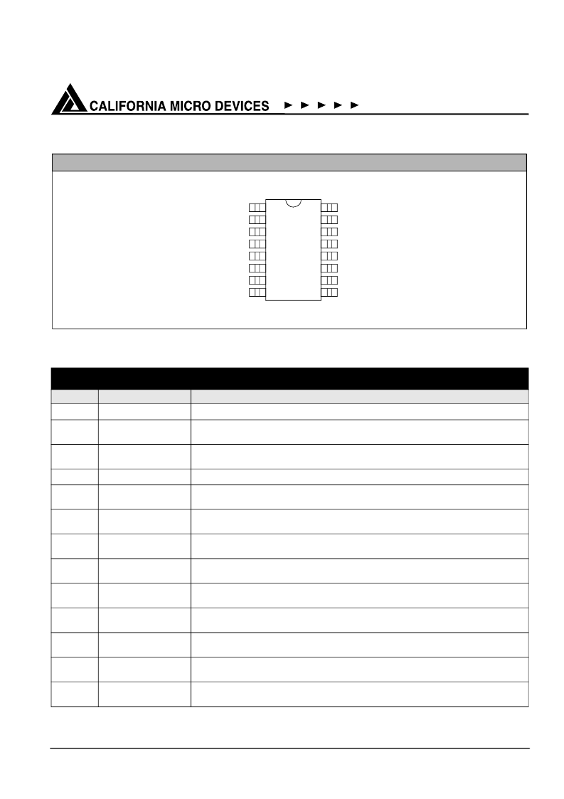
PACKAGE / PINOUT DIAGRAM
Note: This drawing is not to scale.
16-pin QSOP
1
2
3
4
14
13
12
11
5
6
7
10
9
8
15
16
VCC
DDC2_CONN
DDC2_CTLR
VSS
DDC1_CONN
DDC1_CTLR
SYNC2_CONN
SYNC2_CTLR
VCC
RGB1
RGB2
VSS
RGB3
SYNC1_CONN
SYNC1_CTLR
VCC
Top View
相關(guān)PDF資料 |
PDF描述 |
|---|---|
| PACVGA105 | VGA Port Companion Circuit |
| PACVGA105Q | VGA Port Companion Circuit |
| PACVGA105QR | VGA Port Companion Circuit |
| PACVGA200 | VGA PORT COMPANION CIRCUIT |
| PACVGA200Q | VGA PORT COMPANION CIRCUIT |
相關(guān)代理商/技術(shù)參數(shù) |
參數(shù)描述 |
|---|---|
| PACVGA-101 | 制造商:CALMIRCO 制造商全稱:California Micro Devices Corp 功能描述:VGA PROTECTION AND TERMINATION NETWORK |
| PACVGA-101R | 制造商:CALMIRCO 制造商全稱:California Micro Devices Corp 功能描述:VGA PROTECTION AND TERMINATION NETWORK |
| PACVGA-101T | 制造商:CALMIRCO 制造商全稱:California Micro Devices Corp 功能描述:VGA PROTECTION AND TERMINATION NETWORK |
| PACVGA105 | 制造商:CALMIRCO 制造商全稱:California Micro Devices Corp 功能描述:VGA Port Companion Circuit |
| PACVGA105Q | 制造商:CALMICRO 功能描述: |
發(fā)布緊急采購,3分鐘左右您將得到回復(fù)。