- 您現(xiàn)在的位置:買(mǎi)賣(mài)IC網(wǎng) > PDF目錄369945 > PA34 (Electronic Theatre Controls, Inc.) POWER OPERATIONAL AMPLIFIERS PDF資料下載
參數(shù)資料
| 型號(hào): | PA34 |
| 廠商: | Electronic Theatre Controls, Inc. |
| 元件分類(lèi): | 運(yùn)算放大器 |
| 英文描述: | POWER OPERATIONAL AMPLIFIERS |
| 中文描述: | 功耗運(yùn)算放大器 |
| 文件頁(yè)數(shù): | 5/5頁(yè) |
| 文件大小: | 66K |
| 代理商: | PA34 |

APEX MICROTECHNOLOGY CORPORATION
TELEPHONE (520) 690-8600
FAX (520) 888-3329
ORDERS (520) 690-8601
EMAIL prodlit@apexmicrotech.com
PA34U REV. 1 JANUARY 2001 2001 Apex Microtechnology Corp.
C
5
OPERATING
CONSIDERATIONS
PA34
V
BOOST
pin requires approximately 10
–
12mA of current.
Dynamically it represents 1K
impedance. The maximum
voltage that can be applied to V
BOOST
is 40 volts with
respect to
–
V
S
. There is no limit to the difference between
+V
S
and V
BOOST
.
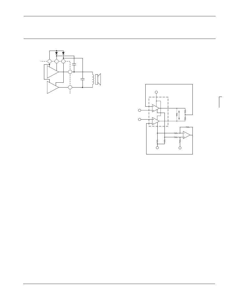
Figure 3 shows a bootstrap which dynamically couples the
output waveform onto the V
BOOST
pin. This causes V
BOOST
to swing positive from it's initial value, which is equal to +V
S
-0.7 V (one diode drop), an amount equal to the output. In
other words, if V
BOOST
was initially 19.3, and the output
swings positive 18 Volts, the voltage on the V
BOOST
pin
will swing to 19.3 -0.7 + 18 or 36.6. The capacitor needs
to be sized based on a 1K
impedance and the lowest
frequency required by the circuit. For example, 20Hz will
require > 8uF.
I
SENSE
The I
SENSE
pin is in series with the negative half of the
output stage only. Current will
fl
ow through this pin only when
negative current is being outputted. The current that
fl
ows
in this pin is the same current that
fl
ows in the output (if
–
1A
fl
ows in the output, the I
SENSE
pin will have 1A of
current
fl
ow, if +1A
fl
ows in the output the I
SENSE
pin will
have 0 current
fl
ow).
The resistor choice is arbitrary and is selected to provide
whatever voltage drop the engineer desires, up to a maximum
of 1.0 volt. However, any voltage dropped across the resistor
will subract from the swing to rail. For instance, assume a
+/
–
12 volt power supply and a load that requires +/
–
1A. With
no current sense resistor the output could swing +/
–
10.2
volts. If a 1
resistor is used for current sense (which
will drop 1 Volt at 1 Amp) then the output could swing
+10.2,
–
9.2 Volts.
Figure 4 shows the PA34 I
SENSE
feature being used to
obtain a Transconductance function. In this example, ampli
fi
er
"A" is the master and ampli
fi
er "B" is the slave. Feedback
from sensing resistors R
S
is applied to the summing network
and scaled to the inverting input of ampli
fi
er "A" where it is
compared to the input voltage. The current sensing feedback
imparts a Transconductance feature to the ampli
fi
ers transfer
function. In other words, the voltage developed across the
sensing resistors is directly proportional to the output current.
Using this voltage as a feedback source allows expressing
the gain of the circuit in amperes vs input voltage. The transfer
funcion is approximately:
I
L
= (V
IN
–
V
REF
) *R
IN
/ R
FB
/ R
s
In the illustration, resistors R
IN
, R
FB
and R
S
determine
gain.
V
BIAS
should be set midway between +V
s
and -V
s
, Vref
is usually ground in dual supply systems or used for level
translation in single supply systems.
MOUNTING PRECAUTIONS
1. Always use a heat sink. Even unloaded, the PA34 can
dissipate up to 3.6 watts. A thermal washer or thermal
grease should always be used.
2. Avoid bending the leads. Such action can lead to internal
damage.
3. Always fasten the tab to the heat sink before the leads are
soldered to
fi
xed terminals.
4. Strain relief must be provided if there is any probability of
axial stress to the leads.
10
3
7
5
8
+V
S
≤
20V
D
B1
D
B2
C
B1
SPEAKER
C
B2
FIGURE 3. SIMPLE BOOTSTRAPPING IMPROVES POSITIVE
OUTPUT SWING. CONNECT PINS 3 AND 10 TO V
S
IF NOT
USED. TYPICAL CURRENTS ARE 12
m
A EACH.
A
B
V
BIAS
+VS
VIN
VREF
–
VS OR GND
RS
RS
IL
RL
RIN
RIN
R
R
RFB
R
FB
FIGURE 4. I
SENSE
TRANSCONDUCTANCE BRIDGING
AMPLIFIER
相關(guān)PDF資料 |
PDF描述 |
|---|---|
| PA44 | HIGH VOLTAGE POWER OPERATIONAL AMPLIFIER |
| PA7540JI-15 | PA7540 PEEL Array? Programmable Electrically Erasable Logic Array |
| PA7540JN-15 | PA7540 PEEL Array? Programmable Electrically Erasable Logic Array |
| PA7540JNI-15 | PA7540 PEEL Array? Programmable Electrically Erasable Logic Array |
| PA7540J-15 | PA7540 PEEL Array? Programmable Electrically Erasable Logic Array |
相關(guān)代理商/技術(shù)參數(shù) |
參數(shù)描述 |
|---|---|
| PA-34 | 制造商:Centralab 功能描述:switch wafers 制造商:Electro Switch Corp 功能描述: 制造商:ELECTROSWITCH 功能描述: |
| PA3408NL | 制造商:Pulse Engineering Inc 功能描述: |
| PA340CC | 功能描述:IC AMP PWR 350V 120MA 7DDPAK RoHS:是 類(lèi)別:未定義的類(lèi)別 >> 未定義的系列 系列:* 標(biāo)準(zhǔn)包裝:2,500 系列:* |
| PA341 | 功能描述:按鈕開(kāi)關(guān) PUSHBUTTON SW ON-OFF 15A@125vAC 1/4"QUICK RoHS:否 制造商:C&K Components 觸點(diǎn)形式:2 NC - 2 NO 開(kāi)關(guān)功能:ON ? OFF 電流額定值:4 A 電壓額定值 AC:12 V to 250 V 電壓額定值 DC:12 V to 50 V 功率額定值: 安裝風(fēng)格:Through Hole 照明:Illuminated 照明顏色:None IP 等級(jí):IP 40 端接類(lèi)型:Solder 觸點(diǎn)電鍍:Silver 執(zhí)行器:Square 蓋顏色: 封裝: 可燃性等級(jí):UL 94 V-0 |
| PA3413NL | 制造商:Pulse Electronics Corporation 功能描述:- Bulk |
發(fā)布緊急采購(gòu),3分鐘左右您將得到回復(fù)。