- 您現(xiàn)在的位置:買賣IC網(wǎng) > PDF目錄367748 > PA16A (Electronic Theatre Controls, Inc.) POWER OPERATIONAL AMPLIFIERS PDF資料下載
參數(shù)資料
| 型號: | PA16A |
| 廠商: | Electronic Theatre Controls, Inc. |
| 元件分類: | 運(yùn)算放大器 |
| 英文描述: | POWER OPERATIONAL AMPLIFIERS |
| 中文描述: | 功耗運(yùn)算放大器 |
| 文件頁數(shù): | 4/4頁 |
| 文件大?。?/td> | 62K |
| 代理商: | PA16A |
APEX MICROTECHNOLOGY CORPORATION
5980 NORTH SHANNON ROAD
TUCSON, ARIZONA 85741
USA
APPLICATIONS HOTLINE: 1 (800) 546-2739
OPERATING
CONSIDERATIONS
PA16
PA16A
.1K
1.0K
FREQUENCY, F (Hz)
0.001
0.1
1
HARMONIC DISTORTION
D
10K
0.01
100K
1
3
4
TIME, t (
μ
S)
–
15
5
15
PULSE RESPONSE
–
10
0
10
2
5
–
5
PULSE RESPONSE
O
O
–
.2
–
.1
0
.1
.2
.3
–
.3
10K
FREQUENCY, F (Hz)
LOADING EFFECTS
D
–
1.2
–
.6
0
.1M
100
1K
–
1.5
–
.9
–
.3
TIME, t (
μ
S)
0
.5
1.0
1.5
O
O
0
A
V
= 10
V
PS
=
±
15V
V
IN
=
±
.2V, tr = 50ns
V
IN
=
±
1V, tr = 100ns
LOAD = 10
I
O
= 150mA
I
O
= 400mA
P
O
= .5W
R
L
= 4
P
O
= 5W
R
L
= 4
P
O
= 25W
R
L
= 2
GENERAL
Please read Application Note 1 "General Operating Considerations" which covers
stability, supplies, heat sinking, mounting, current limit, SOA interpretation, and
specification interpretation. Visit www.apexmicrotech.com for design tools that help
automate tasks such as calculations for stability, internal power dissipation, current
limit; heat sink selection; Apex
’
s complete Application Notes library; Technical Seminar
Workbook; and Evaluation Kits.
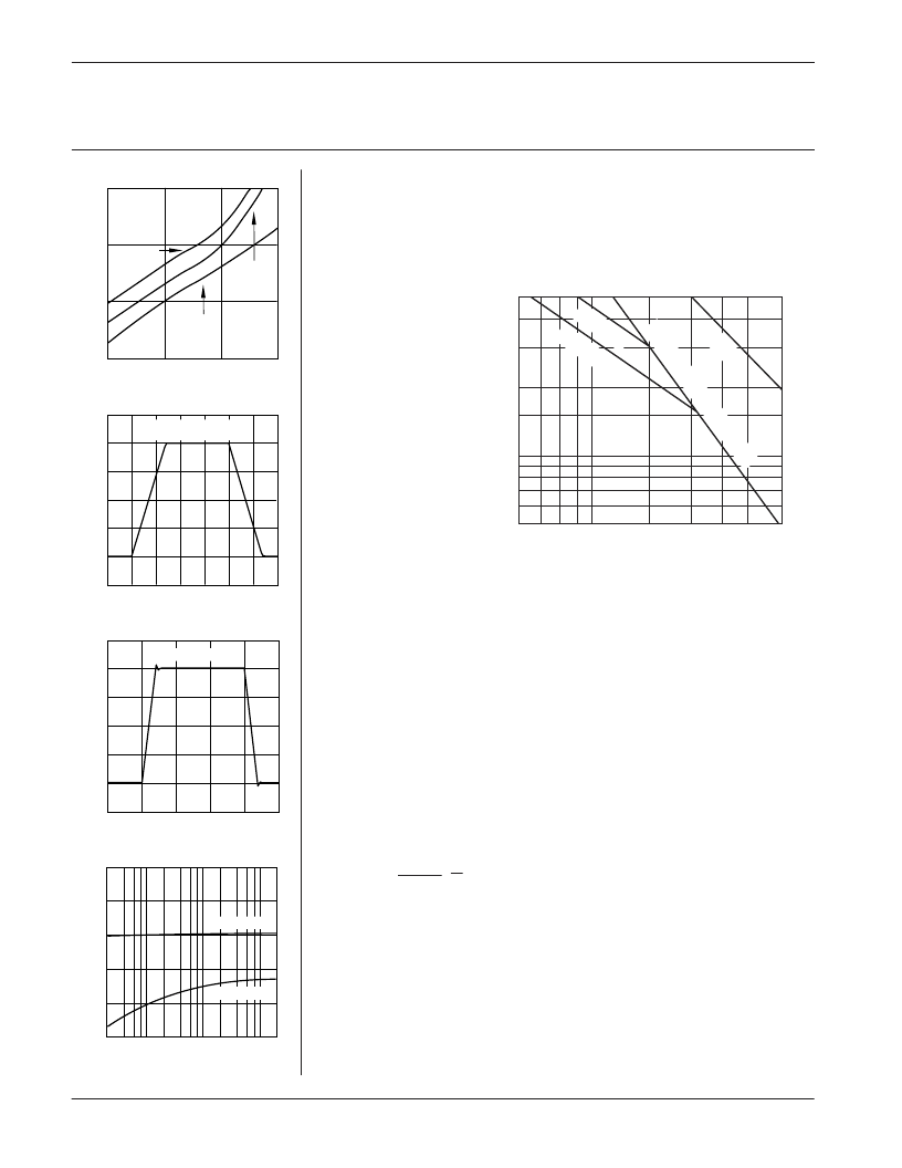
SAFE OPERATING
AREA (SOA)
The SOA curves com-
bine the effect of all limits
for this Power Op Amp.
For a given application,
the direction and magni-
tude of the output cur-
rent should be calculated
or
measured
and
checked against the SOA
curves. This is simple for
resistive loads but more
complex for reactive and
EMF generating loads.
The following guidelines
may save extensive ana-
lytical efforts:
SUPPLY TO OUTPUT DIFFERENTIAL VOLTAGE V
S
–
V
O
(V)
The amplifier can handle any EMF generating or reactive load and short circuits to
the supply rails or shorts to common if the current limits are set as follows at
T
C
= 85
°
C.
SHORT TO
±
V
±
V
S
C, L OR EMF LOAD
SHORT TO
COMMON
18V
15V
10V
.9A
1.0A
1.6A
1.8A
2.1A
3.2A
These simplified limits may be exceeded with further analysis using the operating
conditions for a specific application.
CURRENT LIMIT
Proper operation requires the use of two current limit resistors, connected as shown
in the external connection diagram. The minimum value for R
is 0.12 ohm, however
for optimum reliability it should be set as high as possible. Refer to the
“
General
Operating Considerations
”
section of the handbook for current limit adjust details.
.65
I
LIM
(A)
0.01
R
CL
=
DEVICE MOUNTING
The case (mounting flange) is electrically isolated and should be mounted directly to
a heatsink with thermal compound. Screws with Belville spring washers are recom-
mended to maintain positive clamping pressure on heatsink mounting surfaces. Long
periods of thermal cycling can loosen mounting screws and increase thermal resis-
tance.
Since the case is electrically isolated (floating) with respect to the internal circuits it
is recommended to connect it to common or other convenient AC ground potential.
t=5m
sed tt eodbekow
Tc=60
°
C
Tc=85
°
C
5.0
4.0
3.0
2.0
1.5
1.0
0.8
0.6
0.5
6
7
8
10
9
15
20
25
30
38
O
S
–
V
S
相關(guān)PDF資料 |
PDF描述 |
|---|---|
| PA1A-12V | THE SLIM POWER RELAY |
| PA1A-18V | THE SLIM POWER RELAY |
| PA1A-24V | THE SLIM POWER RELAY |
| PA1A-5V | THE SLIM POWER RELAY |
| PA1A-5VV | THE SLIM POWER RELAY |
相關(guān)代理商/技術(shù)參數(shù) |
參數(shù)描述 |
|---|---|
| PA16BP223KAB15 | 制造商:VISHAY 制造商全稱:Vishay Siliconix 功能描述:Knob Potentiometer |
| PA16BP223KFB15 | 制造商:VISHAY 制造商全稱:Vishay Siliconix 功能描述:Knob Potentiometer |
| PA16BP223KLB15 | 制造商:VISHAY 制造商全稱:Vishay Siliconix 功能描述:Knob Potentiometer |
| PA16BP223MAB15 | 制造商:VISHAY 制造商全稱:Vishay Siliconix 功能描述:Knob Potentiometer |
發(fā)布緊急采購,3分鐘左右您將得到回復(fù)。