- 您現(xiàn)在的位置:買賣IC網(wǎng) > PDF目錄367748 > PA12 (Electronic Theatre Controls, Inc.) POWER OPERATIONAL AMPLIFIERS PDF資料下載
參數(shù)資料
| 型號: | PA12 |
| 廠商: | Electronic Theatre Controls, Inc. |
| 元件分類: | 運算放大器 |
| 英文描述: | POWER OPERATIONAL AMPLIFIERS |
| 中文描述: | 功耗運算放大器 |
| 文件頁數(shù): | 4/4頁 |
| 文件大小: | 106K |
| 代理商: | PA12 |
SHORT TO
±
V
S
C, L, OR EMF LOAD
.30A
.58A
.87A
1.5A
2.4A
2.9A
4.2A
SHORT TO
COMMON
2.4A
2.9A
3.7A
4.1A
4.9A
6.3A
8.0A
±
V
S
50V
40V
35V
30V
25V
20V
15V
These simplified limits may be exceeded with further analysis using the operat-
ing conditions for a specific application.
CURRENT LIMITING
Refer to Application Note 9, "Current Limiting", for details of both
fixed and foldover current limit operation. Visit the Apex web site
at www.apexmicrotech.com for a copy of the Power Design
spreadsheet (Excel) which plots current limits vs. steady state
SOA. Beware that current limit should be thought of as a +/–20%
function initially and varies about 2:1 over the range of –55
°
C to
125
°
C.
For fixed current limit, leave pin 7 open and use equations 1 and 2.
R
CL
= 0.65/L
CL
I
CL
= 0.65/R
CL
Where:
I
CL
is the current limit in amperes.
R
CL
is the current limit resistor in ohms.
For certain applications, foldover current limit adds a slope to
the current limit which allows more power to be delivered to the
load without violating the SOA. For maximum foldover slope,
ground pin 7 and use equations 3 and 4.
(1)
(2)
0.65 + (Vo * 0.014)
I
CL
=
(3)
R
CL
0.65 + (Vo * 0.014)
R
CL
=
(4)
I
CL
Where:
Vo is the output voltage in volts.
Most designers start with either equation 1 to set R
CL
for the
desired current at 0v out, or with equation 4 to set R
at the
maximum output voltage. Equation 3 should then be used to plot
the resulting foldover limits on the SOA graph. If equation 3 results
in a negative current limit, foldover slope must be reduced. This
can happen when the output voltage is the opposite polarity of the
supply conducting the current.
In applications where a reduced foldover slope is desired, this
can be achieved by adding a resistor (R
) between pin 7 and
ground. Use equations 4 and 5 with this new resistor in the circuit.
0.65 +10.14 + R
FO
I
CL
=
(5)
R
CL
0.65 +10.14 + R
FO
R
CL
=
(6)
I
CL
Where:
R
FO
is in K ohms.
OPERATING
CONSIDERATIONS
PA12 PA12A
GENERAL
Please read Application Note 1, which covers stability, supplies,
heatsinking, mounting, current limit, SOA interpretation, and speci-
fication interpretation. Additional information can be found in the
application notes. For information on the package outline, heatsinks,
and mounting hardware, consult the “Accessory and Package
Mechanical Data” section of the handbook.
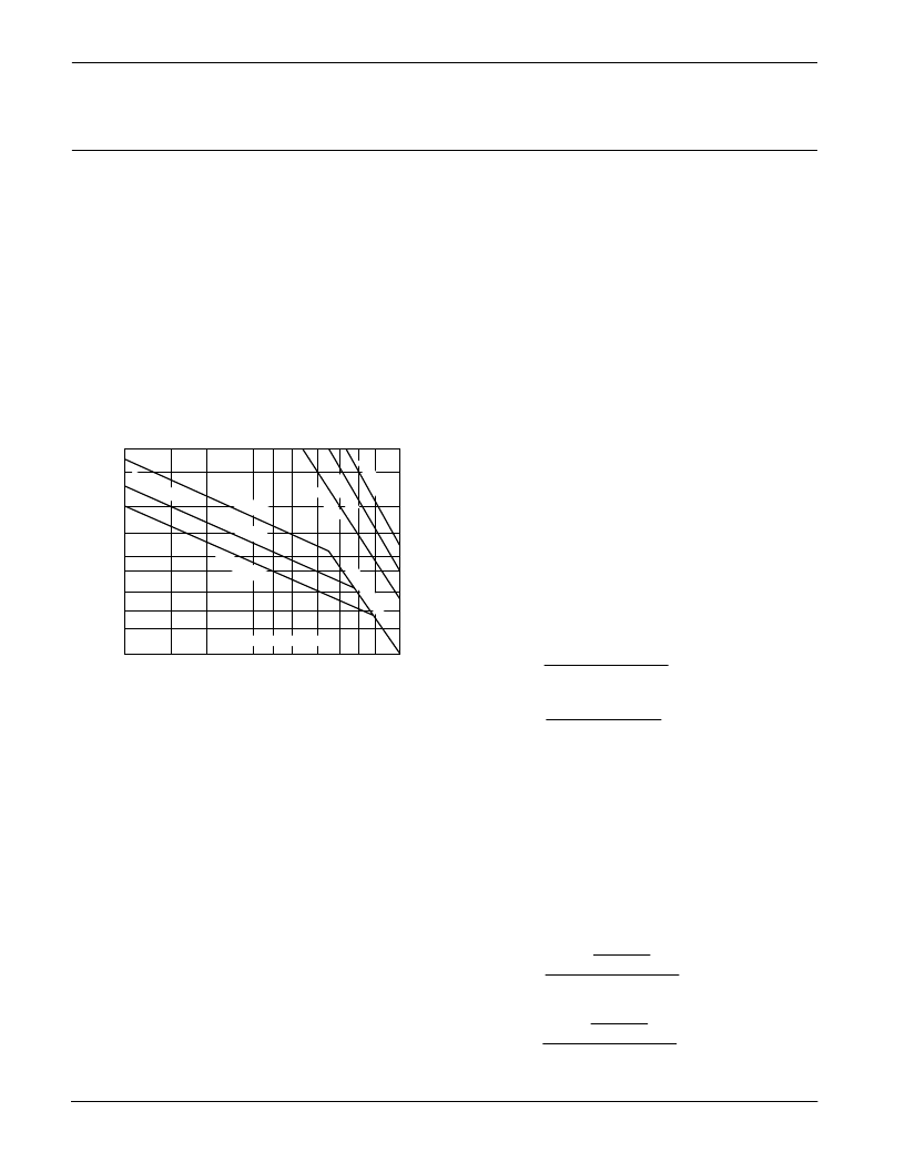
SAFE OPERATING AREA (SOA)
The output stage of most power amplifiers has three distinct
limitations:
1. The current handling capability of the transistor geometry and
the wire bonds.
2. The second breakdown effect which occurs whenever the
simultaneous collector current and collector-emitter voltage
exceeds specified limits.
3. The junction temperature of the output transistors.
The SOA curves combine the effect of all limits for this Power Op
Amp. For a given application, the direction and magnitude of the
output current should be calculated or measured and checked
against the SOA curves. This is simple for resistive loads but more
complex for reactive and EMF generating loads. However, the
following guidelines may save extensive analytical efforts.
1. Capacitive and dynamic* inductive loads up to the following
maximum are safe with the current limits set as specified.
CAPACITIVE LOAD
I
LIM
= 5A
200
μ
F
500
μ
F
2.0mF
7.0mF
25mF
60mF
150mF
INDUCTIVE LOAD
I
LIM
= 5A
5mH
15mH
50mH
150mH
500mH
1,000mH
2,500mH
±
V
S
50V
40V
35V
30V
25V
20V
15V
I
LIM
= 10A
125
μ
F
350
μ
F
850
μ
F
2.5mF
10mF
20mF
60mF
I
LIM
= 10A
2.0mH
3.0mH
5.0mH
10mH
20mH
30mH
50mH
*If the inductive load is driven near steady state conditions, allowing the output
voltage to drop more than 8V below the supply rail with I
= 15A or 25V below
the supply rail with I
= 5A while the amplifier is current limiting, the inductor
must be capacitively coupled or the current limit must be lowered to meet SOA
criteria.
2. The amplifier can handle any EMF generating or reactive load
and short circuits to the supply rail or common if the current
limits are set as follows at T
C
= 25
°
C:
5.0
3.0
2.0
1.5
1.0
.7
.3
10
20
25
30
35 40
50
60 70
SUPPLY TO OUTPUT DIFFERENTIAL VOLTAGE V –V (V)
O
S
S
.5
t=1s
T
C
= 85°C
sed tt
15
80
100
10
15
T
C
= 125°C
T
C
= 25°C
THERMAL
t=5m
t=05s
SECOND BREAKDOWN
This data sheet has been carefully checked and is believed to be reliable, however, no responsibility is assumed for possible inaccuracies or omissions. All specifications are subject to change without notice.
PA12U REV. M MARCH 1999
1999 Apex Microtechnology Corp.
相關(guān)PDF資料 |
PDF描述 |
|---|---|
| PA12A | POWER OPERATIONAL AMPLIFIERS |
| PA15 | HIGH VOLTAGE POWER OPERATIONAL AMPLIFIERS |
| PA15A | HIGH VOLTAGE POWER OPERATIONAL AMPLIFIERS |
| PA16 | POWER OPERATIONAL AMPLIFIERS |
| PA16A | POWER OPERATIONAL AMPLIFIERS |
相關(guān)代理商/技術(shù)參數(shù) |
參數(shù)描述 |
|---|---|
| PA-12 | 制造商:Electro Switch Corp 功能描述: 制造商:ELECTROSWITCH 功能描述: 制造商:Autonics Corporation 功能描述:SENSOR FOR CONTROLLER 110/220 VAC 制造商:CENTRALAB 功能描述:Operational Amplifier, Single AMP, Hybrid, 9 Pin, Metal Can |
| PA12,00ST RU FRA | 制造商:Sosiete des Composants RECORD 功能描述:Bulk |
| PA12 | 制造商:SPC Multicomp 功能描述:TERMINAL BLOCK 41A 12 WAY |
| PA12_09 | 制造商:CIRRUS 制造商全稱:Cirrus Logic 功能描述:Power Operational Amplifier |
| PA-120 | 制造商:MEANWELL 制造商全稱:Mean Well Enterprises Co., Ltd. 功能描述:120W Single Output Power Supply or Battery Charger |
發(fā)布緊急采購,3分鐘左右您將得到回復(fù)。