- 您現(xiàn)在的位置:買(mǎi)賣(mài)IC網(wǎng) > PDF目錄367723 > P80C550EFAA (NXP SEMICONDUCTORS) IC SPI EEPROM/512X8 SMT SO-8 PDF資料下載
參數(shù)資料
| 型號(hào): | P80C550EFAA |
| 廠商: | NXP SEMICONDUCTORS |
| 元件分類(lèi): | 微控制器/微處理器 |
| 英文描述: | IC SPI EEPROM/512X8 SMT SO-8 |
| 中文描述: | 8-BIT, 8 MHz, MICROCONTROLLER, PQCC44 |
| 封裝: | PLASTIC, LCC-44 |
| 文件頁(yè)數(shù): | 9/28頁(yè) |
| 文件大小: | 190K |
| 代理商: | P80C550EFAA |
第1頁(yè)第2頁(yè)第3頁(yè)第4頁(yè)第5頁(yè)第6頁(yè)第7頁(yè)第8頁(yè)當(dāng)前第9頁(yè)第10頁(yè)第11頁(yè)第12頁(yè)第13頁(yè)第14頁(yè)第15頁(yè)第16頁(yè)第17頁(yè)第18頁(yè)第19頁(yè)第20頁(yè)第21頁(yè)第22頁(yè)第23頁(yè)第24頁(yè)第25頁(yè)第26頁(yè)第27頁(yè)第28頁(yè)
Philips Semiconductors
Product specification
80C550/83C550/87C550
80C51 8-bit microcontroller family
4K/128 OTP/ROM/ROMless, 8 channel 8 bit A/D, watchdog timer
1998 May 01
9
Sample A/D Routines
The following routines demonstrate two methods of operating the
A/D converter. The first method uses polling to determine when the
A/D conversion is complete. The second method uses the A/D
interrupt to flag the end of conversion.
The routine ReadAD will start a read of the A/D channel identified by
R7, and wait for the conversion to complete, polling the A/D interrupt
flag. The result is returned in the accumulator.
ReadAD:MOV A,#08h
ORL
MOV ADCON,A;
ADLoop: MOV A,ADCON
JNB
MOV A,ADAT
MOV ADCON,#0
RET
;Basic A/D start command.
;Add channel # to be read.
;Start A/D.
;Get A/D status.
A,R7
ACC.4,ADLoop;Wait for ADCI (A/D ;finished).
;Get conversion result
;Clear ADCI.
The routine StartAD will start a read of the A/D channel identified by
R7 and exit back to the calling program. When the conversion is
complete, the A/D interrupt occurs, calling the A/D interrupt service
routine. The result of the conversion is returned in register R6.
StartAD: MOV A,#08h
ORL
MOV ADCON,A
RET
.
.
.
ORG 2Bh
ADInt:
MOV R6,ADAT
MOV ADCON,#0
RETI
;Basic A/D start command.
;Add channel # to be read.
;Start A/D.
A,R7
;A/D interrupt address.
;Get conversion result.
;Clear ADCI.
R
S
V
ANALOG
INPUT
C
S
C
C
To Comparator
+
I
N
I
N+1
Sm
N+1
Sm
N
Rm
N+1
Rm
N
Multiplexer
Rm = 0.5 - 3 k
CS + CC = 15pF maximum
RS = Recommended < 9.6 k
for 1 LSB @ 12MHz
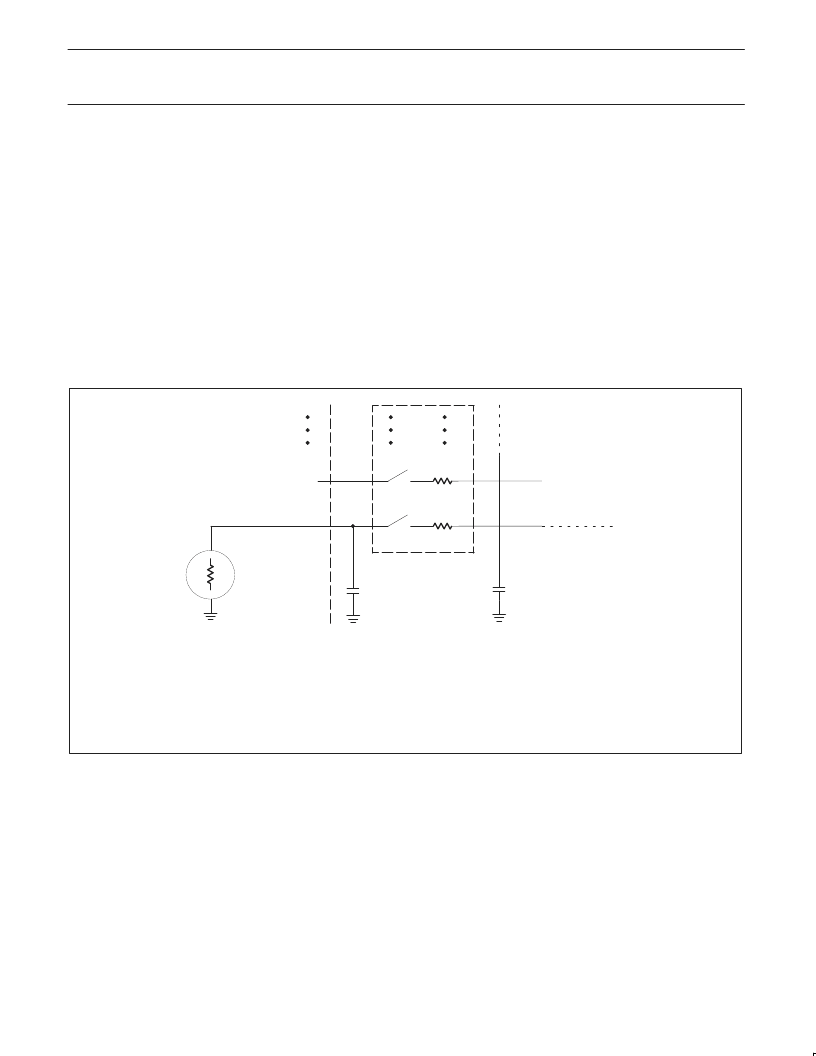
NOTE:
Because the analog to digital converter has a sampled-data comparator, the input looks capacitive to a source. When a conversion
is initiated, switch Sm closes for 8tcy (8
μ
s @ 12MHz crystal frequency) during which time capacitance Cs + Cc is charged. It should
be noted that the sampling causes the analog input to present a varying load to an analog source.
SU00199
Figure 3. A/D Input: Equivalent Circuit
相關(guān)PDF資料 |
PDF描述 |
|---|---|
| P83C550EFAA | IC, AT25256. 8S1/JEDEC SOIC 8 |
| P87C550EFAA | AT25F1024 1M BIT SPI FLASH - SO8 |
| P80C557E4EBB | Single-chip 8-bit microcontroller |
| P80C557E8 | 8 BIT MICROCONTROLLER |
| P83C557E8 | 8 BIT MICROCONTROLLER |
相關(guān)代理商/技術(shù)參數(shù) |
參數(shù)描述 |
|---|---|
| P80C550EFAA-T | 制造商:未知廠家 制造商全稱(chēng):未知廠家 功能描述:8-Bit Microcontroller |
| P80C550EFK | 制造商:未知廠家 制造商全稱(chēng):未知廠家 功能描述:8-Bit Microcontroller |
| P80C550EFN | 制造商:未知廠家 制造商全稱(chēng):未知廠家 功能描述:8-Bit Microcontroller |
| P80C552 | 制造商:PHILIPS 制造商全稱(chēng):NXP Semiconductors 功能描述:Single-chip 8-bit microcontroller |
| P80C552EBA | 制造商:PHILIS 功能描述: 制造商:PHILPS 功能描述: |
發(fā)布緊急采購(gòu),3分鐘左右您將得到回復(fù)。