- 您現(xiàn)在的位置:買賣IC網(wǎng) > PDF目錄296753 > P4SMCA36CA61 (VISHAY SEMICONDUCTORS) 400 W, BIDIRECTIONAL, SILICON, TVS DIODE, DO-214AC PDF資料下載
參數(shù)資料
| 型號(hào): | P4SMCA36CA61 |
| 廠商: | VISHAY SEMICONDUCTORS |
| 元件分類: | 參考電壓二極管 |
| 英文描述: | 400 W, BIDIRECTIONAL, SILICON, TVS DIODE, DO-214AC |
| 封裝: | PLASTIC, SMA, 2 PIN |
| 文件頁數(shù): | 1/3頁 |
| 文件大小: | 39K |
| 代理商: | P4SMCA36CA61 |
P4SMA6.8A Series
Vishay Semiconductors
formerly General Semiconductor
Document Number 88367
www.vishay.com
9-Apr-02
1
Surface Mount TRANSZORB
Transient Voltage Suppressors
V(BR) Unidirectional
6.8 to 540V
V(BR) Bidirectional
6.8 to 220V
Peak Pulse Power 400W
Extended
Voltage
Range*
Devices for Bidirectional Applications
For bi-directional devices, use suffix CA (e.g. P4SMA10CA). Electrical characteristics apply in both directions.
Maximum Ratings & Thermal Characteristics Ratings at 25°C ambient temperature unless otherwise specified.
Parameter
Symbol
Value
Unit
Peak power dissipation with a 10/1000
s waveform(1)(2)(Fig. 1)
PPPM
400
W
Peak pulse current with a 10/1000
s waveform(1) (Fig. 3)
IPPM
See Next Table
A
Power dissipation on infinite heatsink, TA = 50°C
PM(AV)
1.0
W
Peak forward surge current 8.3ms single half sine-wave
IFSM
40
A
uni-directional only(2)
Thermal resistance junction to ambient air(3)
R
θJA
120
°C/W
Thermal resistance junction to leads
R
θJL
30
°C/W
Operating junction and storage temperature range
TJ, TSTG
–65 to +150
°C
Notes: (1) Non-repetitive current pulse, per Fig. 3 and derated above TA = 25°C per Fig. 2. Rating is 300W above 91V.
(2) Mounted on 0.2 x 0.2” (5.0 x 5.0mm) copper pads to each terminal
(3) Mounted on minimum recommended pad layout
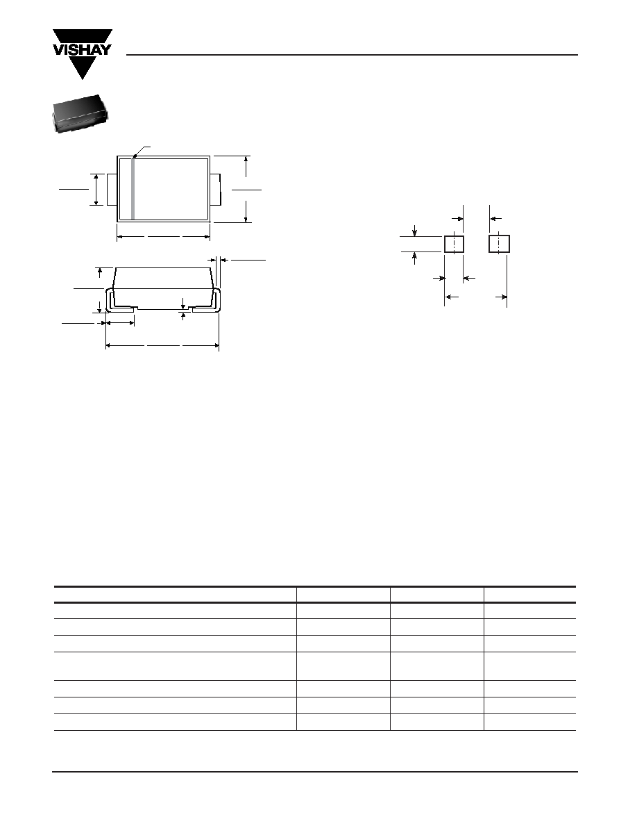
0.157 (3.99)
0.177 (4.50)
0.006 (0.152)
0.012 (0.305)
0.030 (0.76)
0.060 (1.52)
0.008 (0.203) MAX.
0.194 (4.93)
0.208 (5.28)
0.100 (2.54)
0.110 (2.79)
0.078 (1.98)
0.090 (2.29)
0.049 (1.25)
0.065 (1.65)
Cathode Band
Dimensions in inches
and (millimeters)
DO-214AC
(SMA)
Features
Plastic package has Underwriters Laboratory
Flammability Classification 94V-0
Optimized for LAN protection applications
Ideal for ESD protection of data lines in accordance with
IEC 1000-4-2 (IEC801-2)
Ideal for EFT protection of data lines in accordance with
IEC1000-4-4 (IEC801-4)
Low profile package with built-in strain relief for
surface mounted applications
Glass passivated junction
Low incremental surge resistance, excellent clamping
capability
400W peak pulse power capability with a 10/1000
s wave-
form, repetition rate (duty cycle): 0.01% (300W above 91V)
Very Fast response time
*Voltages above 220V available Q2-2002
Mechanical Data
Case: JEDEC DO-214AC molded plastic over
passivated chip
Terminals: Solder plated, solderable per MIL-STD-750,
Method 2026. High temperature soldering guaranteed:
250°C/10 seconds at terminals.
Polarity: For uni-directional types the band denotes the
cathode, which is positive with respect to the anode
under normal TVS operation.
Mounting Position: Any
Weight: 0.002oz., 0.064g
Packaging Codes – Options (Antistatic):
51 – 1K per Bulk box, 20K/carton
61 – 1.8K per 7” plastic Reel (12mm tape), 36K/carton
5A – 7.5K per 13” plastic Reel (12mm tape), 75K/carton
0.094 MAX.
(2.38 MAX.)
0.220
(5.58) REF
0.066 MIN.
(1.68 MIN.)
0.052 MIN.
(1.32 MIN.)
Mounting Pad Layout
相關(guān)PDF資料 |
PDF描述 |
|---|---|
| P4SMCA10CA51-E3 | 400 W, BIDIRECTIONAL, SILICON, TVS DIODE, DO-214AC |
| P4SMCA20CA51-E3 | 400 W, BIDIRECTIONAL, SILICON, TVS DIODE, DO-214AC |
| P4SMCA30CA51-E3 | 400 W, BIDIRECTIONAL, SILICON, TVS DIODE, DO-214AC |
| P4SMCA7.5CA5A-E3 | 400 W, BIDIRECTIONAL, SILICON, TVS DIODE, DO-214AC |
| P5-105-00 | 50/125 um, MULTI MODE, DUPLEX FIBER OPTIC CONNECTOR, PLUG |
相關(guān)代理商/技術(shù)參數(shù) |
參數(shù)描述 |
|---|---|
| P4SOCK4231.4FAN | 制造商:Intel 功能描述:P4 Socket 423 1.4GHz with fan |
| P4SPA+-O | 制造商:Supermicro Computer Inc 功能描述:SUPERMICRO MBD-P4SPA+-O - Bulk |
| P4SPE - B | 制造商:Supermicro Computer Inc 功能描述:- Bulk |
| P4SPOOL | 制造商:Pentair Technical Products / Hoffman 功能描述:Cable Spool 4in, Qty 10 , 4", Plastic 制造商:Pentair Technical Products / Hoffman 功能描述:CABLE SPOOL, PLASTIC, BLACK, Cable Organizer Type:Cable Spool, For Use With:Heavy Duty or Seismic Racks, Color:Black, Kit Contents:10 spools and mounting screws, Material:Plastic , RoHS Compliant: Yes |
| P4SSMJ100APT | 制造商:CHENMKO 制造商全稱:Chenmko Enterprise Co. Ltd. 功能描述:GLASS PASSIVATED JUNCTION TRANSIENT VOLTAGE SUPPRESSOR |
發(fā)布緊急采購(gòu),3分鐘左右您將得到回復(fù)。