- 您現(xiàn)在的位置:買賣IC網(wǎng) > PDF目錄378031 > OP471 (Analog Devices, Inc.) High Speed, Low Noise Quad Operational Amplifier PDF資料下載
參數(shù)資料
| 型號: | OP471 |
| 廠商: | Analog Devices, Inc. |
| 英文描述: | High Speed, Low Noise Quad Operational Amplifier |
| 中文描述: | 高速,低噪聲四運(yùn)算放大器 |
| 文件頁數(shù): | 7/16頁 |
| 文件大?。?/td> | 314K |
| 代理商: | OP471 |
REV. A
OP471
–7–
500
5k
V
1
20V p-p
1/4
OP471
50
50k
CHANNEL SEPARATION = 20 LOG
V
1
V
2
/ 1000
V
2
1/4
OP471
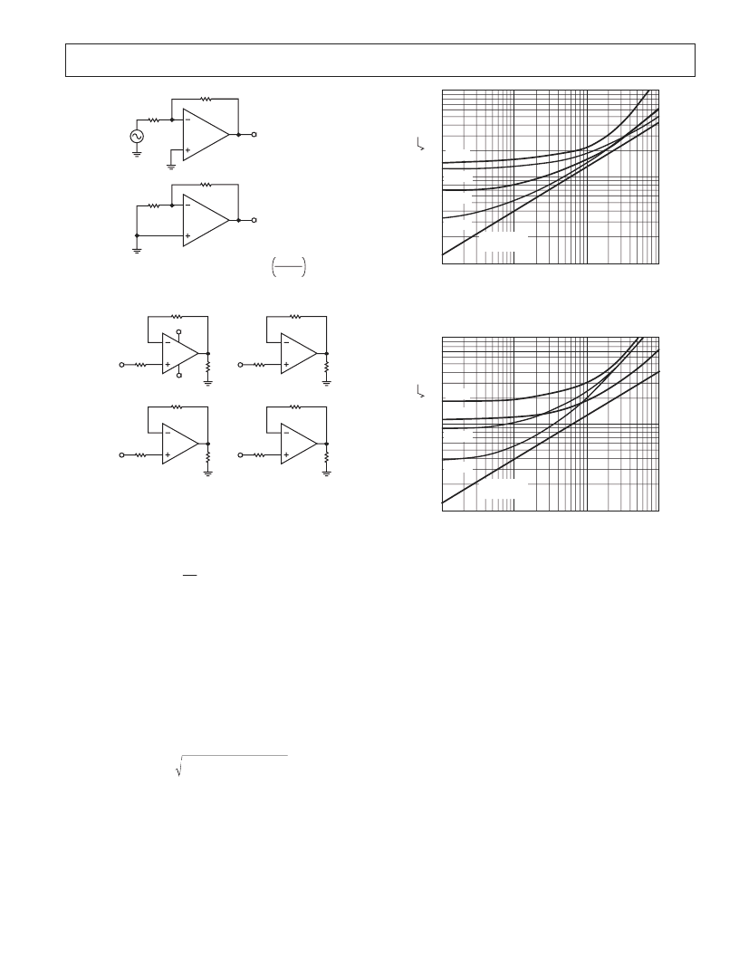
Figure 2. Channel Separation Test Circuit
7
6
5
1
2
3
+1V
+18V
4
–18V
11
A
+1V
B
D
14
13
12
–1V
C
8
9
10
–1V
Figure 3. Burn-In Circuit
APPLICATIONS INFORMATION
Voltage and Current Noise
The OP471 is a very low-noise quad op amp, exhibiting a typical
voltage noise of only 6.5
Hz
@ 1 kHz. The low noise character-
istic of the OP471 is, in part, achieved by operating the input
transistors at high collector currents since the voltage noise is
inversely proportional to the square root of the collector current.
Current noise, however, is directly proportional to the square
root of the collector current. As a result, the outstanding voltage
noise performance of the OP471 is gained at the expense of current
noise performance which is typical for low noise amplifiers.
To obtain the best noise performance in a circuit, it is vital to
understand the relationship between voltage noise (e
n
), current
noise (i
n
), and resistor noise (e
t
).
Total Noise and Source Resistance
The total noise of an op amp can be calculated by:
E
e
i R
e
n
n
S
t
=
( )
+
(
)
+
( )
2
2
2
where:
E
n
= total input referred noise
e
n
= op amp voltage noise
i
n
= op amp current noise
e
t
= source resistance thermal noise
R
S
= source resistance
The total noise is referred to the input and at the output would
be amplified by the circuit gain.
RS – SOURCE RESISTANCE –
100
1
100
100k
T
10
10k
1k
OP11
OP400
OP471
OP470
RESISTOR
NOISE ONLY
Figure 4. Total Noise vs. Source Resistance (Including
Resistor Noise) at 1 kHz
RS – SOURCE RESISTANCE –
100
1
100
100k
T
10
10k
1k
OP11
OP400
OP471
OP470
RESISTOR
NOISE ONLY
Figure 5. Total Noise vs. Source Resistance (Including
Resistor Noise) at 10 Hz
Figure 4 shows the relationship between total noise at 1 kHz
and source resistance. For R
S
< 1 k
W
the total noise is domi-
nated by the voltage noise of the OP471. As R
S
rises above 1 k
W
,
total noise increases and is dominated by resistor noise rather
than by voltage or current noise of the OP471. When R
S
exceeds
20 k
W
, current noise of the OP471 becomes the major contributor
to total noise.
Figure 5 also shows the relationship between total noise and source
resistance, but at 10 Hz. Total noise increases more quickly
than shown in Figure 4 because current noise is inversely pro-
portional to the square root of frequency. In Figure 5, current
noise of the OP471 dominates the total noise when R
S
> 5 k
W
.
From Figures 4 and 5, it can be seen that to reduce total noise,
source resistance must be kept to a minimum. In applications
with a high source resistance, the OP400, with lower current
noise than the OP471, will provide lower total noise.
相關(guān)PDF資料 |
PDF描述 |
|---|---|
| OP471FY | High Speed, Low Noise Quad Operational Amplifier |
| OP471GP | High Speed, Low Noise Quad Operational Amplifier |
| OP471GS | High Speed, Low Noise Quad Operational Amplifier |
| P-DSO-20 | integrated modulator-mixer for transmit path |
| P0102BL-5AA4 | 0.25A SCRs |
相關(guān)代理商/技術(shù)參數(shù) |
參數(shù)描述 |
|---|---|
| OP-471 | 制造商:AD 制造商全稱:Analog Devices 功能描述:HIGH SPEED, LOW NOISE QUAD OPERATIONAL AMPLIFIER |
發(fā)布緊急采購,3分鐘左右您將得到回復(fù)。