- 您現在的位置:買賣IC網 > PDF目錄383687 > OP297A (OPTEK TECHNOLOGY INC) Plastic Infrared Emitting Diode PDF資料下載
參數資料
OPTEK reserves the right to make changes at any time in order to improve design and to supply the best product possible.
OPTEK Technology Inc. —
1645 Wallace Drive, Carrollton, Texas 75006
Phone: (972) 323-2200 or (800) 341-4747
FAX: (972) 323-2396 sensors@optekinc.com www.optekinc.com
Issue A 05/07
Page 5 of 8
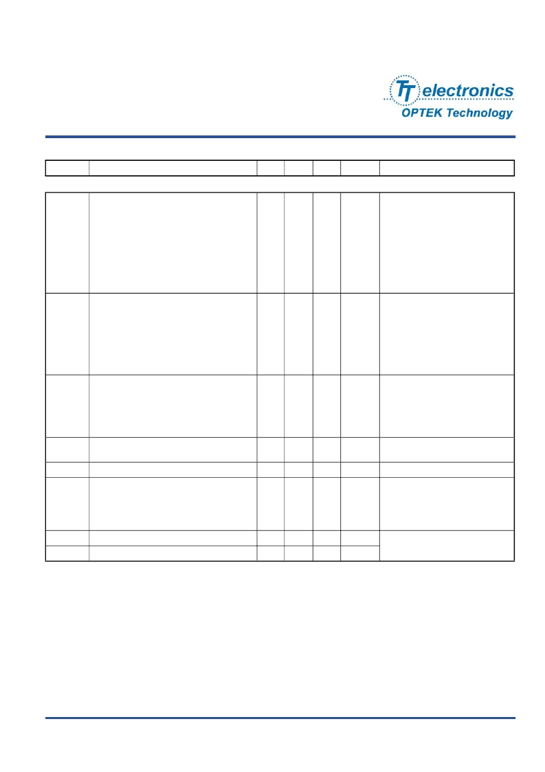
Plastic Infrared Emitting Diode
OP290 Series
Electrical Characteristics
(T
A
= 25
°
C unless otherwise noted)
SYMBOL
PARAMETER
MIN
TYP
MAX
UNITS
TEST CONDITIONS
Input Diode
V
F
Forward Voltage
(3)
OP290, OP295
OP291, OP296
OP292, OP297
OP293, OP298 (A, B, C)
OP298 (AA, AB, AC, AD)
OP294, OP299
-
-
-
-
-
-
-
-
-
-
-
-
4.00
2.00
1.75
2.00
2.00
1.50
V
I
F
= 1.50 A
I
F
= 100 mA
I
F
= 20 mA
I
F
= 1.50 A
I
F
= 100 mA
I
F
= 5 mA
I
R
Reverse Current
(3)
OP290, OP292
OP291, OP293, OP298 (A, B, C), OP296
OP298 (AA, AB, AC, AD)
OP294, OP299
OP295, OP297
-
-
-
-
-
-
-
-
-
-
10
100
100
10
10
μA
V
R
= 5 V
V
R
= 2 V
V
R
= 2 V
V
R
= 2 V
V
R
= 5 V
λ
P
Wavelength at Peak Emission
OP290, OP291, OP292, OP293, OP294,
OP295, OP296, OP297, OP298 (A, B, C),
OP299
OP298 (AA, AB, AC, AD)
-
-
890
875
-
-
nm
I
F
= 10 mA
B
Spectral Bandwidth between Half Power
Points
-
80
-
nm
I
F
= 10 mA
λ
P
/
T
Spectral Shift with Temperature
-
+0.18
-
nm/°C
I
F
= Constant
θ
HP
Emission Angle at Half Power Points
OP290, OP291, OP292, OP294
OP293
OP295, OP296, OP297, OP299
OP298
-
-
-
-
50
60
20
25
-
-
-
-
Degree
I
F
= 20 mA
t
r
Output Rise Time
-
500
-
ns
I
F(PK)
=100 mA, PW=10 μs, and
D.C.=10.0%
t
f
Output Fall Time
-
250
-
ns
相關PDF資料 |
PDF描述 |
|---|---|
| OP297B | Plastic Infrared Emitting Diode |
| OP297C | Plastic Infrared Emitting Diode |
| OP298AB | Plastic Infrared Emitting Diode |
| OP298AC | Plastic Infrared Emitting Diode |
| OP298AD | Plastic Infrared Emitting Diode |
相關代理商/技術參數 |
參數描述 |
|---|---|
| OP297A | 制造商:TT Electronics / OPTEK Technology 功能描述:IR Emitting Diode |
| OP297AB | 功能描述:紅外發(fā)射源 Infrared 890nm RoHS:否 制造商:Fairchild Semiconductor 波長:880 nm 射束角:+/- 25 輻射強度: 最大工作溫度:+ 100 C 最小工作溫度:- 40 C 封裝 / 箱體:Side Looker 封裝:Bulk |
| OP297ARC/883 | 制造商:未知廠家 制造商全稱:未知廠家 功能描述:Voltage-Feedback Operational Amplifier |
| OP-297ARC/883 | 制造商:AD 制造商全稱:Analog Devices 功能描述:DUAL LOW BIAS CURRENT PRECISION OPERATIONAL AMPLIFIER |
| OP297AZ | 制造商:Rochester Electronics LLC 功能描述:DUAL PRECISION LOW IB OP - Bulk |
發(fā)布緊急采購,3分鐘左右您將得到回復。