- 您現(xiàn)在的位置:買賣IC網(wǎng) > PDF目錄224594 > N3764-4 (3M ELECTRONIC PRODUCTS DIVISION) MALE, STRAIGHT TWO PART BOARD CONNECTOR, WIRE WRAP PDF資料下載
參數(shù)資料
| 型號: | N3764-4 |
| 廠商: | 3M ELECTRONIC PRODUCTS DIVISION |
| 元件分類: | 電路板相疊連接器 |
| 英文描述: | MALE, STRAIGHT TWO PART BOARD CONNECTOR, WIRE WRAP |
| 文件頁數(shù): | 3/4頁 |
| 文件大?。?/td> | 55K |
| 代理商: | N3764-4 |
3M Interconnect Solutions Division
6801 River Place Blvd.
Austin, TX 78726-9000
For technical, sales or ordering information call
800-225-5373
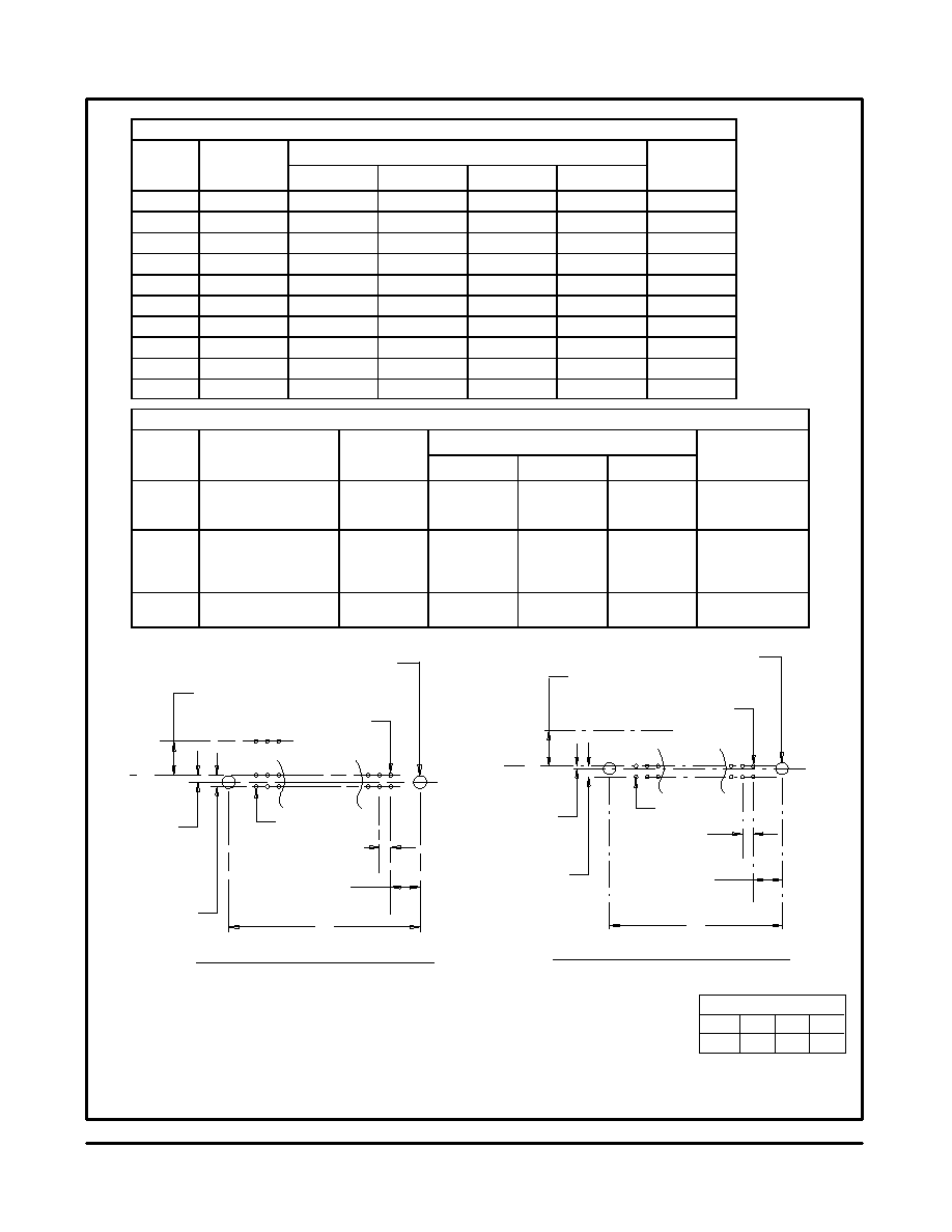
.100
″ .100″ Latch/Ejector Header
3 Wall, Straight & Right Angle, High Temp Option
Table 1
Pin
3M Part
Dimensions
Polarization
Notches
Pn
Quantity
3M Part
Number
A
B
C
D
Notches
Provided
10
3793
1.26 [32.1]
1.105 [28.07]
.865 [21.97]
.71 [18.0]
B C
14
3314
1.46 [37.2]
1.305 [33.15]
1.065 [27.05]
.91 [23.1]
B C
16
3408
1.56 [39.7]
1.405 [35.69]
1.165 [29.59]
1.01 [25.6]
A B C
20
3428
1.76 [44.8]
1.605 [40.77]
1.365 [34.67]
1.21 [30.7]
A B C
26
3429
2.06 [52.4]
1.905 [48.39]
1.665 [42.29]
1.51 [38.3]
A B C
34
3431
2.46 [62.6]
2.305 [58.55]
2.065 [52.45]
1.91 [48.5]
A B C
40
3432
2.76 [70.2]
2.605 [66.17]
2.365 [60.07]
2.21 [56.1]
A B C
50
3433
3.26 [82.9]
3.105 [78.87]
2.865 [72.77]
2.71 [68.8]
A B C
60
3372
3.76 [95.6]
3.605 [91.57]
3.365 [85.47]
3.21 [81.5]
A B C
64
3764
3.96 [100.7]
3.805 [96.65]
3.565 [90.55]
3.41 [86.6]
A B C
Table 2
3M Part
Number
Ct
t T il
Dii
E
Pin Cross Section
Dii
G
Number
Suffix
Contact Tail
Dimension E
Dimension F
Diagonals
Corner Radii
Dimension G
-1XX2
-2XX2
Solder Tail for
.062 [1.57]
Thick PC Board
.112
[2.84]
0.0245
± .0005
[0.622]
0.028
± .001
[0.71]
0.0075 Ref
[0.191]
.035
± .003
[0.89] (See Note 3)
-1X03
-2X03
Solder Tail for
.094 [2.39] to
.125 [3.18]
Thick PC Board
.155
[3.94]
0.0245
± .0005
[0.622]
0.028
± .001
[0.71]
0.0075 Ref
[0.191]
.035
± .003
[0.89]
-3X05
-4X05
Wire Wrap Tail for up to
3 Levels of Wire Wrap
.61 Ref
[15.5]
0.0250
± .002
[0.635]
0.035
± .003
[0.90]
0.003 Max
[0.08]
.045
± .003
[1.14]
CL
.41
[10.4]
Max to Edge of PCB
for Daisy Chain
.106
[2.69]
or
.116
[2.95]
(See Note 2)
G Dia
.029
[0.74]
.100
± .003
[2.54]
Position 1
.232
[5.89]
C
Recommended Mounting Hole Pattern
(Right Angle)
.100
± .003
[2.54]
.106
[2.69]
or
.116
[2.95]
(See Note 2)
G Dia
Position 1
.100
± .003
[2.54]
.100
± .003
[2.54]
.060
[1.52]
.300
[7.62]
Side to Side Stackability
B
Recommended Mounting Hole Pattern
(Straight)
.352
[8.94]
Notes:
1. Notches A & C will accomodate 3M Polarizing Keys (3M Part #3518 or M3518).
2. Accepts Rear and Front mounting hardware:
Rear Entry: #4-24 thread cutting screw, 3M Part #3341-5, .116 [2.95] dia mounting hole
Front Entry: (Prior to installation of latch on Straight Versions) #2-56 bolt and nut, 3M Part #3341-6,
.106 [2.69] dia mounting hole
3. The recommended PCB hole size for the kinked tail positions on the .112 solder tail connector is .035
± .002.
Refer to TS-0972 for the positions kinked.
Inch
[mm]
± .005
± .1 ± .01
Tolerance Unless Noted
.0
.00
.000
Inch
[ ] Dimensions for
Reference only
TS-0771-02
Sheet 3 of 4
“Y”
CL
相關PDF資料 |
PDF描述 |
|---|---|
| N3764 | MALE, STRAIGHT TWO PART BOARD CONNECTOR, PRESS FIT |
| N3429 | MALE, STRAIGHT TWO PART BOARD CONNECTOR, PRESS FIT |
| N3431 | MALE, STRAIGHT TWO PART BOARD CONNECTOR, PRESS FIT |
| N3433 | MALE, STRAIGHT TWO PART BOARD CONNECTOR, PRESS FIT |
| N3372 | MALE, STRAIGHT TWO PART BOARD CONNECTOR, PRESS FIT |
相關代理商/技術參數(shù) |
參數(shù)描述 |
|---|---|
| N3764-4205EB | 制造商:3M Electronic Products Division 功能描述:,HAZMAT - Bulk |
| N3764-4305EB | 制造商:3M Electronic Products Division 功能描述:,HAZMAT - Bulk |
| N3764-5002RB | 功能描述:集管和線殼 64P HDR RA 4 WALL LTCH EJECT RoHS:否 產(chǎn)品種類:1.0MM Rectangular Connectors 產(chǎn)品類型:Headers - Pin Strip 系列:DF50 觸點類型:Pin (Male) 節(jié)距:1 mm 位置/觸點數(shù)量:16 排數(shù):1 安裝風格:SMD/SMT 安裝角:Right 端接類型:Solder 外殼材料:Liquid Crystal Polymer (LCP) 觸點材料:Brass 觸點電鍍:Gold 制造商:Hirose Connector |
| N3764-5003 | 制造商:3M Electronic Products Division 功能描述:CONN EJECTOR HDR HDR 64 POS 2.54MM SLDR RA TH - Bulk |
| N3764-5003RB | 制造商:3M Electronic Products Division 功能描述:CONN EJECTOR HDR HDR 64 POS 2.54MM SLDR RA TH - Bulk |
發(fā)布緊急采購,3分鐘左右您將得到回復。