- 您現(xiàn)在的位置:買賣IC網(wǎng) > PDF目錄376215 > MXO45-5I (Electronic Theatre Controls, Inc.) Metal DIP Clock Oscillator PDF資料下載
參數(shù)資料
| 型號: | MXO45-5I |
| 廠商: | Electronic Theatre Controls, Inc. |
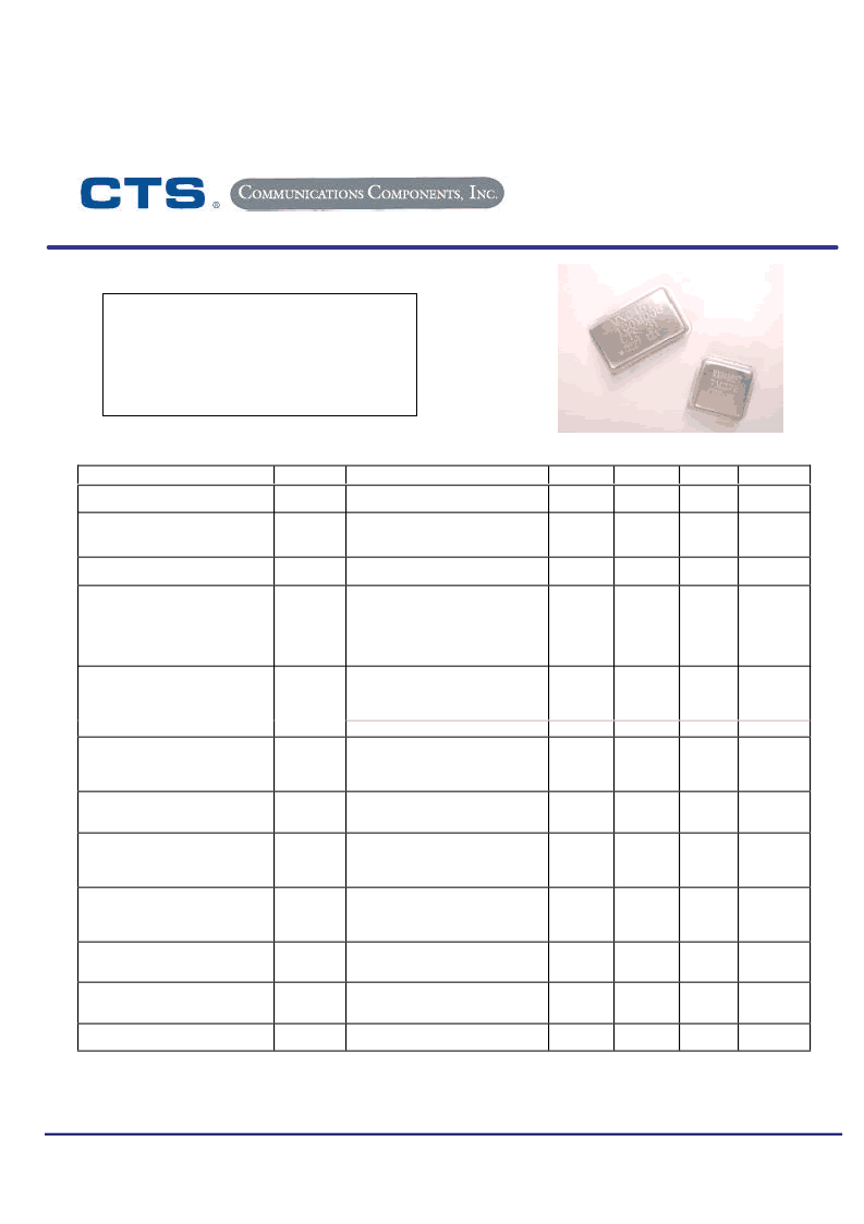
| 英文描述: | Metal DIP Clock Oscillator |
| 中文描述: | 金屬雙酯時鐘振蕩器 |
| 文件頁數(shù): | 1/3頁 |
| 文件大小: | 86K |
| 代理商: | MXO45-5I |

CTS
Communications Components, Inc
.
171 Covington Drive
Bloomingdale, IL 60108
630-924-3500
Document No. 008-0258-0
Page 1 of 3
Rev. A ECO# 16710
Electrical Characteristics
Parameter
Output Frequency Range
Symbol
f
O
Conditions
Min
Typical
Max
Unit
-
1.0
-
105.561
MHz
Stability
(Note 1)
(
See Ordering Information)
Supply Voltage
f/f
-
-
-
20,25,50
or 100
ppm
V
CC
-
4.5
5.0
5.5
V
Operating Supply Current
I
CC
1.0 MHz to 7.0 MHz C
L
=50pF
7.1 MHz to 25 MHz C
L
=50pF
25.1 MHz to 50 MHz C
L
=50pF
50.1 MHz to 70 MHz C
L
=30pF
80.1 MHz to 105.561 MHz C
L
=15pF
-
-
-
-
-
5
15
30
40
45
12
25
40
60
85
mA
1.0 MHz to 50 MHz
50.1 MHz to 70 MHz
70.1 MHz to 105.561 MHz
1.0 MHz to 105.561 MHz
-
-
-
-
-
-
-
-
50
30
15
10
PF
Output Load
CMOS
TTL
Output Voltage Levels
Logic '1' Level
C
L
TTL
Logic '0' Level
Output Current
V
OH
V
OH
V
OL
CMOS Load
TTL Load
CMOS or TTL Load
Vcc-0.4V
Vcc-0.6V
-
-
-
-
-
-
0.4
V
I
OH
I
OL
SYM
V
OH
= 3.9V V
CC
= 4.5V
V
OL
= 0.4V V
CC
= 4.5V
-
-
-
-
-16
+16
mA
Output Duty Cycle
(50% Level)
1.0 MHz to 50 MHz
50.1 MHz to 70 MHz
70.1 MHz to 105.561 MHz
45
40
45
-
55
60
55
%
Rise & Fall Time (10% - 90% Level)
t
R
, t
F
1.0 MHz to 25 MHz C
L
=50pF
25.1 MHz to 70 MHz C
L
=30pF
70.1 MHz to 105.561 MHz C
L
=15pF
-
-
-
5
3
2
8
5
3
nS
Start Up Time
-
-
-
10
mS
Enable Function
(Note 2)
-
See ‘Enable Truth Table’ on
Page 2 or 3
-
-
-
-
Phase Jitter
tj
Peak - Peak
-
30
50
pS
Notes:
1.
Inclusive of initial tolerance at time of shipment, changes in supply voltage, load, temperature and first year aging at an
average operating temperature of 40 °C.
Reference CTS Application Note 014-0002-0.
2.
MXO45/MXO45HS
Metal DIP
Clock Oscillator
Stability to ±20 PPM
+5.0Vdc Operation
CMOS/TTL Compatible
Operating Temperature to –40°C to +85°C
Output Enable Option
14 Pin and 8 Pin Packages
相關(guān)PDF資料 |
PDF描述 |
|---|---|
| MXO45-6C | Metal DIP Clock Oscillator |
| MXO45-6I | Metal DIP Clock Oscillator |
| MXO45HS | Metal DIP Clock Oscillator |
| MXO45HS-2C | Metal DIP Clock Oscillator |
| MXO45HS-2I | Metal DIP Clock Oscillator |
相關(guān)代理商/技術(shù)參數(shù) |
參數(shù)描述 |
|---|---|
| MXO45-5I-37M0560 | 制造商:CTS Corporation 功能描述:0037.056000 MHZ HYBRID CIRCUIT - Tape and Reel |
| MXO45-6C | 制造商:未知廠家 制造商全稱:未知廠家 功能描述:Metal DIP Clock Oscillator |
| MXO45-6C-40M0000 | 制造商:CTS Corporation 功能描述:0040.000000 MHZ HYBRID CIRCUIT - Tape and Reel |
| MXO45-6C-64M0000 | 制造商:CTS Corporation 功能描述:- Trays |
| MXO45-6I | 制造商:未知廠家 制造商全稱:未知廠家 功能描述:Metal DIP Clock Oscillator |
發(fā)布緊急采購,3分鐘左右您將得到回復(fù)。