- 您現(xiàn)在的位置:買賣IC網(wǎng) > PDF目錄224591 > MWDM2L-51SBST-.250 (GLENAIR INC) 51 CONTACT(S), FEMALE, D MICROMINIATURE CONNECTOR, SOLDER PDF資料下載
參數(shù)資料
| 型號(hào): | MWDM2L-51SBST-.250 |
| 廠商: | GLENAIR INC |
| 元件分類: | D-微型連接器 |
| 英文描述: | 51 CONTACT(S), FEMALE, D MICROMINIATURE CONNECTOR, SOLDER |
| 文件頁數(shù): | 2/4頁 |
| 文件大?。?/td> | 478K |
| 代理商: | MWDM2L-51SBST-.250 |
2006 Glenair, Inc.
CAGE Code 06324/0CA77
Printed in U.S.A.
GLENAIR, INC. 1211 AIR WAY GLENDALE, CA 91201-2497 818-247-6000 FAX 818-500-9912
www.glenair.com
C-11
E-Mail: sales@glenair.com
Micro-D
PCB
A
B
C
D
E
F
G
H
J
K
L
M
N
P
DIMENSIoNS
Layout
A Max.
B
C Max.
D Max.
E Max.
F
G
H
J Max.
K
In.
mm.
In.
±.003
mm.
± 0.08
In.
mm.
In.
mm.
In.
mm.
In.
±.004
mm.
±0.10
In.
±.010
mm.
±0.25
In.
±.007
mm.
±0.18
In.
mm.
In.
±.010
mm.
±0.25
9P
.790 20.07
.565 14.35
.333 8.46
.184 4.67
.310 7.87
.183 4.65
.333 8.46 1.150 29.21 1.390 35.31
.155
3.94
9S
.790 20.07
.565 14.35
.400 10.16
.250 6.35
.310 7.87
.195 4.95
.333 8.46 1.150 29.21 1.390 35.31
.155
3.94
15P
.940 23.88
.715 18.16
.483 12.27
.184 4.67
.310 7.87
.183 4.65
.333 8.46 1.150 29.21 1.390 35.31
.155
3.94
15S
.940 23.88
.715 18.16
.551 14.00
.250 6.35
.310 7.87
.195 4.95
.333 8.46 1.150 29.21 1.390 35.31
.155
3.94
21P
1.180 29.97
.865 21.97
.633 16.08
.184 4.67
.310 7.87
.183 4.65
.333 8.46 1.450 36.83 1.690 42.93
.155
3.94
21S
1.180 29.97
.865 21.97
.701 17.81
.250 6.35
.310 7.87
.195 4.95
.333 8.46 1.450 36.83 1.690 42.93
.155
3.94
25P
1.275 32.39
.965 24.51
.733 18.62
.184 4.67
.310 7.87
.183 4.65
.333 8.46 1.500 38.10 1.740 44.20
.155
3.94
25S
1.275 32.39
.965 24.51
.801 20.35
.250 6.35
.310 7.87
.195 4.95
.333 8.46 1.500 38.10 1.740 44.20
.155
3.94
31P
1.575 40.01 1.115 28.32
.883 22.43
.184 4.67
.310 7.87
.183 4.65
.333 8.46 1.800 45.72 2.040 51.82
.155
3.94
31S
1.575 40.01 1.115 28.32
.951 24.16
.250 6.35
.310 7.87
.195 4.95
.333 8.46 1.800 45.72 2.040 51.82
.155
3.94
37P
1.875 47.63 1.265 32.13 1.033 26.24
.184 4.67
.310 7.87
.183 4.65
.333 8.46 2.100 53.34 2.340 59.44
.155
3.94
37S
1.875 47.63 1.265 32.13 1.101 27.96
.250 6.35
.310 7.87
.195 4.95
.333 8.46 2.100 53.34 2.340 59.44
.155
3.94
51P
1.775 45.09 1.215 30.86
.983 24.97
.224 5.69
.351 8.92
.183 4.65
.333 8.46 2.000 50.80 2.270 57.64
.155
3.94
51S
1.775 45.09 1.215 30.86 1.051 26.70
.293 7.44
.351 8.92
.195 4.95
.333 8.46 2.000 50.80 2.270 57.64
.155
3.94
100P
2.585 65.66 1.800 45.72 1.383 35.13
.270 6.86
.394 10.01
.183 4.65
.525 13.34 2.800 71.12 3.250 82.55
.293
7.44
100S
2.585 65.66 1.800 45.72 1.451 36.86
.333 8.46
.394 10.01
.195 4.95
.525 13.34 2.800 71.12 3.250 82.55
.293
7.44
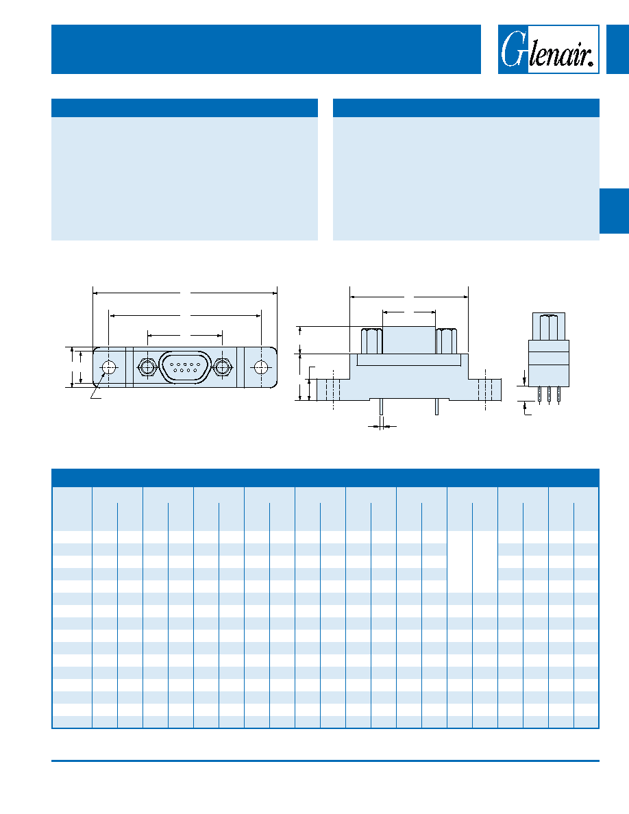
Micro-D Metal Shell Printed Circuit Board Connectors
BS Style Vertical Mount thru-Hole
TAIL LENGH
2 X PCB MTNG HOLES
9-51 CONTACTS .096 ± .005 (2.43 ± 0.13)
100 CONTACTS .125 ± .005 (23.18 ± 0.13)
D
E
J
H
B
.020 ± .002 (0.51± 0.05)
C
F
G
A
K
MAtERIALS AND FINISHES
Connector Shell
Aluminum Alloy 6061 or Stainless Steel, 300
Series, passivated. See Ordering Info for
Plating Options
Insulator, Tray
Liquid Crystal Polymer (LCP)
Interfacial Seal
Flourosilicone Rubber, Blue
Pin Contact
Beryllium Copper Gold over Nickel Plating
Socket Contact
Copper Alloy Gold Over Nickel Plating
PCB Terminals
Gold Plated Copper Alloy, Solder Dipped
Hardware
300 Series Stainless Steel
Encapsulant
Epoxy Resin Hysol EE4215
PERFoRMANCE SPECIFICAtIoNS
Current Rating
3 AMP
DWV
600 VAC Sea level
Insulation Resistance
5000 Megohms Minimum
Contact Resistance
8 Milliohms Maximum
Low Level Contact Resist.
32 Milliohms Maximum
Magnetic Permeability
2 Maximum
Operating Temperature
-55° C. to +150° C.
Shock, Vibration
50 g., 20g.
Mating Force
(10 Ounces) X (# of Contacts)
± .015 (0.38)
相關(guān)PDF資料 |
PDF描述 |
|---|---|
| MWDM2L-9PSMR | 9 CONTACT(S), MALE, D MICROMINIATURE CONNECTOR, SURFACE MOUNT |
| MWDM2L-51-2PSMR | 51 CONTACT(S), MALE, D MICROMINIATURE CONNECTOR, SURFACE MOUNT |
| MWDM2L-51-2SSMR | 51 CONTACT(S), FEMALE, D MICROMINIATURE CONNECTOR, SURFACE MOUNT |
| MWS020ZJY3V | 1-OUTPUT 20 W DC-DC REG PWR SUPPLY MODULE |
| MWS5101ELS | 256 X 4 STANDARD SRAM, 350 ns, PDIP22 |
相關(guān)代理商/技術(shù)參數(shù) |
參數(shù)描述 |
|---|---|
| MWDM2L-51SCBR-.110 | 功能描述:D-Sub微型D連接器 MICR D PCB CON 51SKT CNT RoHS:否 制造商:3M Electronic Solutions Division 位置/觸點(diǎn)數(shù)量:26 排數(shù):2 安裝風(fēng)格:SMD/SMT 安裝角:Right 端接類型:Solder 型式:Female |
| MWDM2L-51SCBR-.125 | 功能描述:D-Sub微型D連接器 MICR D PCB CON 51SKT CNT RoHS:否 制造商:3M Electronic Solutions Division 位置/觸點(diǎn)數(shù)量:26 排數(shù):2 安裝風(fēng)格:SMD/SMT 安裝角:Right 端接類型:Solder 型式:Female |
| MWDM2L-51SCBR-.140 | 功能描述:D-Sub微型D連接器 MICR D PCB CON 51SKT CNT RoHS:否 制造商:3M Electronic Solutions Division 位置/觸點(diǎn)數(shù)量:26 排數(shù):2 安裝風(fēng)格:SMD/SMT 安裝角:Right 端接類型:Solder 型式:Female |
| MWDM2L-51SCBR-.150 | 功能描述:D-Sub微型D連接器 MICR D PCB CON 51SKT CNT POST.032"PNL RoHS:否 制造商:3M Electronic Solutions Division 位置/觸點(diǎn)數(shù)量:26 排數(shù):2 安裝風(fēng)格:SMD/SMT 安裝角:Right 端接類型:Solder 型式:Female |
| MWDM2L-51SCBR-.150-429 | 制造商:Glenair Inc 功能描述:MICRO-D CONNECTORS - Bulk |
發(fā)布緊急采購,3分鐘左右您將得到回復(fù)。