- 您現(xiàn)在的位置:買賣IC網(wǎng) > PDF目錄359234 > MT90820 (Zarlink Semiconductor Inc.) Large Digital Switch PDF資料下載
參數(shù)資料
| 型號: | MT90820 |
| 廠商: | Zarlink Semiconductor Inc. |
| 英文描述: | Large Digital Switch |
| 中文描述: | 大型數(shù)字開關(guān) |
| 文件頁數(shù): | 19/37頁 |
| 文件大?。?/td> | 573K |
| 代理商: | MT90820 |
第1頁第2頁第3頁第4頁第5頁第6頁第7頁第8頁第9頁第10頁第11頁第12頁第13頁第14頁第15頁第16頁第17頁第18頁當前第19頁第20頁第21頁第22頁第23頁第24頁第25頁第26頁第27頁第28頁第29頁第30頁第31頁第32頁第33頁第34頁第35頁第36頁第37頁
MT90820
Data Sheet
19
Zarlink Semiconductor Inc.
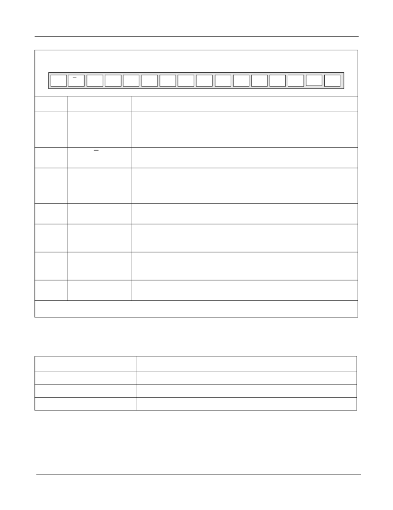
Table 13 - Connection Memory Bits
Table 14 - CAB Bits Programming for Different Data Rates
JTAG Support
The MT90820 JTAG interface conforms to the Boundary-Scan standard IEEE1149.1. This standard specifies a
design-for-testability technique called Boundary-Scan test (BST). The operation of the boundary-scan circuitry is
controlled by an external test access port (TAP) Controller.
Bit
Name
Description
15
LPBK
Per Channel Loopback.
When 1, the STi
n channel
m data comes from the STo
n
channel
m. For proper per channel loopback operations, set the delay offset register
bits OFn[2:0] to zero for the streams which are in the loopback mode. Refer to the
section Loopback Control or Connection Memory Control for more details.
14
V/C
Variable /Constant Throughput Delay.
This bit is used to select between the
variable (low) and the constant delay (high) modes on a per-channel basis.
13
MC
Message Channel.
When 1, the contents of the connection memory are output on the
corresponding output channel and stream. Only the lower byte (bit 7 - bit 0) will be
output to the ST-BUS output pins. When 0, the contents of the connection memory
are the data memory address of the switched input channel and stream.
12
CSTo
Control ST-BUS output.
This bit is output on the CSTo pin one channel early. The
CSTo bit for stream 0 is output first.
11
OE
Output Enable.
This bit enables the ST-BUS output drivers on a per-channel basis.
When 1, the output driver functions normally. When 0, the output driver is in a high-
impedance state.
10 - 8,
7
(Note 1)
SAB3-0
Source Stream Address Bits.
The binary value is the number of the data stream for
the source of the connection.
6 - 0
(Note 1)
CAB6-0
Source Channel Address Bits.
The binary value is the number of the channel for the
source of the connection.
Note 1: If bit 13 (MC) of the corresponding connection memory location is 1 (device in message mode), then these entire 8 bits (SAB0, CAB6
- CAB0) are output on the output channel and stream associated with this location.
Data Rate
CAB Bits Used to Determine the Source Channel of the Connection
2.048 Mb/s
CAB4 to CAB0 (32 channel/input stream)
4.096 Mb/s
CAB5 to CAB0 (64 channel/input stream)
8.192 Mb/s
CAB6 to CAB0 (128 channel/input stream)
7
6
5
4
3
2
1
0
8
9
10
11
12
13
CAB0
CAB1
CAB2
CAB6
SAB0
CAB3
CAB4
CAB5
SAB1
SAB2
SAB3
OE
CSTo
14
V/C
15
MC
LPBK
相關(guān)PDF資料 |
PDF描述 |
|---|---|
| MT90820AL | Large Digital Switch |
| MT90820AL1 | Large Digital Switch |
| MT90823AL1 | 3V Large Digital Switch |
| MT90823 | 3V Large Digital Switch |
| MT90823AB | 3V Large Digital Switch |
相關(guān)代理商/技術(shù)參數(shù) |
參數(shù)描述 |
|---|---|
| MT90820AL | 制造商:Microsemi Corporation 功能描述:SWIT FABRIC 2K X 2K/1K X 1K/512 X 512 131.072MBPS 5V 100MQFP - Trays |
| MT90820AL1 | 制造商:Microsemi Corporation 功能描述:SWIT FABRIC 2K X 2K/1K X 1K/512 X 512 131.072MBPS 5V 100MQFP - Trays 制造商:MICROSEMI CONSUMER MEDICAL PRODUCT GROUP 功能描述:IC DGTL SWITCH 2048X2048 100MQFP 制造商:Microsemi Corporation 功能描述:IC DGTL SWITCH 2048X2048 100MQFP |
| MT90820AP | 制造商:ZARLINK 制造商全稱:Zarlink Semiconductor Inc 功能描述:Large Digital Switch |
| MT90820AP1 | 制造商:ZARLINK 制造商全稱:Zarlink Semiconductor Inc 功能描述:Large Digital Switch |
| MT90820APR | 制造商:Microsemi Corporation 功能描述:SWIT FABRIC 2K X 2K/1K X 1K/512 X 512 5V 84PLCC - Tape and Reel |
發(fā)布緊急采購,3分鐘左右您將得到回復(fù)。