- 您現(xiàn)在的位置:買賣IC網(wǎng) > PDF目錄383645 > MT9075B (Mitel Networks Corporation) E1 Single Chip Transceiver PDF資料下載
參數(shù)資料
| 型號: | MT9075B |
| 廠商: | Mitel Networks Corporation |
| 英文描述: | E1 Single Chip Transceiver |
| 中文描述: | 素E1單芯片收發(fā)器 |
| 文件頁數(shù): | 21/78頁 |
| 文件大?。?/td> | 347K |
| 代理商: | MT9075B |
第1頁第2頁第3頁第4頁第5頁第6頁第7頁第8頁第9頁第10頁第11頁第12頁第13頁第14頁第15頁第16頁第17頁第18頁第19頁第20頁當(dāng)前第21頁第22頁第23頁第24頁第25頁第26頁第27頁第28頁第29頁第30頁第31頁第32頁第33頁第34頁第35頁第36頁第37頁第38頁第39頁第40頁第41頁第42頁第43頁第44頁第45頁第46頁第47頁第48頁第49頁第50頁第51頁第52頁第53頁第54頁第55頁第56頁第57頁第58頁第59頁第60頁第61頁第62頁第63頁第64頁第65頁第66頁第67頁第68頁第69頁第70頁第71頁第72頁第73頁第74頁第75頁第76頁第77頁第78頁
Preliminary Information
MT9075B
21
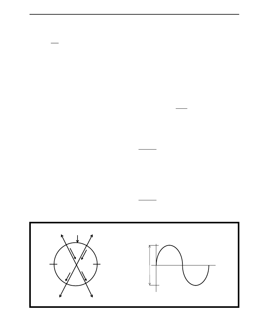
The minimum delay through the receive slip buffer is
approximately two channels and the maximum delay
is approximately 60 channels (see Figure 9).
When the C4b and the E2o clocks are not phase-
locked, the rate at which data is being written into the
slip buffer from the PCM 30 side may differ from the
rate at which it is being read out onto the ST-BUS. If
this situation persists, the delay limits stated in the
previous paragraph will be violated and the slip buffer
will perform a controlled frame slip. That is, the buffer
pointers will be automatically adjusted so that a full
PCM 30 frame is either repeated or lost. All frame
slips occur on PCM 30 frame boundaries.
Two status bits, RSLIP and RSLPD (page 03H,
address 15H), give indication of a slip occurrence
and direction. RSLIP changes state in the event of a
slip. If RSLPD=0, the slip buffer has overflowed and a
frame was lost; if RSLPD=1, a underflow condition
occurred and a frame was repeated. A maskable
interrupt SLPI (page 01H, address 1BH) is also
provided.
Figure 9 illustrates the relationship between the read
and write pointers of the receive slip buffer.
Measuring clockwise from the write pointer, if the
read pointer comes within two channels of the write
pointer a frame slip will occur, which will put the read
pointer 34 channels from the write pointer.
Conversely, if the read pointer moves more than 60
channels from the write pointer, a slip will occur,
which will put the read pointer 28 channels from the
write pointer. This provides a worst case hysteresis
of 13 channels peak (26 channels peak-to-peak) or a
wander tolerance of 208 UI.
Framing Algorithm
The MT9075B contains three distinct framing
algorithms:
basic
frame
multiframe
alignment
and
alignment. Figure 10 is a state diagram that
illustrates these algorithms and how they interact.
alignment,
CRC-4
signalling
multiframe
After power-up, the basic frame alignment framer will
search for a frame alignment signal (FAS) in the PCM
30 receive bit stream. Once the FAS is detected, the
corresponding bit 2 of the non-frame alignment
signal (NFAS) is checked. If bit 2 of the NFAS is zero
a new search for basic frame alignment is initiated. If
bit 2 of the NFAS is one and the next FAS is correct,
the
algorithm
declares
synchronization has been found (i.e., page 03H,
address 10H, bit 7, SYNC is zero).
that
basic
frame
Once basic frame alignment is acquired the
signalling and CRC-4 multiframe searches will be
initiated. The signalling multiframe algorithm will
align to the first multiframe alignment signal pattern
(MFAS = 0000) it receives in the most significant
nibble of channel 16 (page 3, address 10H, bit 6,
MFSYNC = 0). Signalling multiframing will be lost
when two consecutive multiframes are received in
error.
The CRC-4 multiframe alignment signal is a 001011
bit sequence that appears in PCM 30 bit position one
of the NFAS in frames 1, 3, 5, 7, 9 and 11 (see Table
7). In order to achieve CRC-4 synchronization two
CRC-4 multiframe alignment signals must be
received without error (page 03H, address 10H, bit 5,
CRCSYN = 0) within 8 msec.
Figure 9 - Read and Write Pointers in the Slip Buffers
Write Pointer
60 CH
2 CH
47 CH
15 CH
34 CH
28 CH
512 Bit
Elastic
Store
13 CH
-13 CH
Wander Tolerance
Read Pointer
Read Pointer
Read Pointer
Read Pointer
2
相關(guān)PDF資料 |
PDF描述 |
|---|---|
| MT9075B | E1 Single Chip Transceiver(E1單片收發(fā)器) |
| MT9075 | E1 Single Chip Transceiver |
| MT9075A | E1 Single Chip Transceiver |
| MT9075AL | E1 Single Chip Transceiver |
| MT9075AP | E1 Single Chip Transceiver |
相關(guān)代理商/技術(shù)參數(shù) |
參數(shù)描述 |
|---|---|
| MT9075B-1 | 制造商:MITEL 制造商全稱:Mitel Networks Corporation 功能描述:E1 Single Chip Transceiver |
| MT9075BL | 制造商:Microsemi Corporation 功能描述:FRAMER E1 5V 100MQFP - Trays |
| MT9075BL1 | 制造商:Microsemi Corporation 功能描述:FRAMER E1 5V 100MQFP - Trays 制造商:MICROSEMI CONSUMER MEDICAL PRODUCT GROUP 功能描述:IC TXRX SGL E1 W/LIU 100MQFP 制造商:Microsemi Corporation 功能描述:IC TXRX SGL E1 W/LIU 100MQFP |
| MT9075BP | 制造商:Microsemi Corporation 功能描述: |
| MT9075BP1 | 制造商:Microsemi Corporation 功能描述:Single Chip Transceiver 1TX 1RX 2.048Mbps 68-Pin PLCC Tube 制造商:Microsemi Corporation 功能描述:FRAMER E1 5V 68PLCC - Rail/Tube 制造商:Microsemi Corporation 功能描述:PB FREE E1 SINGLE CHIP TRANSCEIVER 制造商:MICROSEMI CONSUMER MEDICAL PRODUCT GROUP 功能描述:IC TXRX SGL E1 W/LIU 68PLCC 制造商:Microsemi Corporation 功能描述:IC TXRX SGL E1 W/LIU 68PLCC |
發(fā)布緊急采購,3分鐘左右您將得到回復(fù)。