- 您現(xiàn)在的位置:買賣IC網(wǎng) > PDF目錄359233 > MT8931CC (Mitel Networks Corporation) CMOS ST-BUS⑩ FAMILY Subscriber Network Interface Circuit Preliminary Information PDF資料下載
參數(shù)資料
| 型號: | MT8931CC |
| 廠商: | Mitel Networks Corporation |
| 英文描述: | CMOS ST-BUS⑩ FAMILY Subscriber Network Interface Circuit Preliminary Information |
| 中文描述: | 意法半導體的CMOS總線⑩家庭用戶網(wǎng)絡(luò)接口電路的初步信息 |
| 文件頁數(shù): | 10/39頁 |
| 文件大小: | 833K |
| 代理商: | MT8931CC |
第1頁第2頁第3頁第4頁第5頁第6頁第7頁第8頁第9頁當前第10頁第11頁第12頁第13頁第14頁第15頁第16頁第17頁第18頁第19頁第20頁第21頁第22頁第23頁第24頁第25頁第26頁第27頁第28頁第29頁第30頁第31頁第32頁第33頁第34頁第35頁第36頁第37頁第38頁第39頁

MT8931C
Data Sheet
10
After successfully completing a transmission, the
internal priority level is reduced from high to low.
The internal priority will only be increased once the
terminal count for the respective level of priority has
been achieved. (e.g., if TE has high priority
internally and externally, it must count 8 consecutive
ones in the D-echo channel. Once this is achieved
and successful transmission has been completed,
the internal priority is reduced to a lower level (i.e.,
count = 9). This terminal will not return to the high
internal priority until 9 consecutive ones have been
monitored on the D-echo channel).
Line Wiring Configuration
The MT8931C can interface to any of the three
wiring configurations which are specified by the
CCITT Recommendation I.430 and ANSI T1.605
(refer to Figures 8 to 10). These consist of a
point-to-point or one of the two point-to- multipoint
configurations (i.e., short passive bus or the
extended passive bus). The selection of line
configurations is performed using the timing bit (B4
of NT Mode Control Register).
For the short passive bus, TE devices are connected
at random points along the cable. However, for the
extended passive bus all connection points are
grouped at the far end of the cable from the NT.
For an NT SNIC in fixed timing mode, the VCO and
Rx filters/peak detectors are disabled and the
threshold voltage is fixed. However, for a TE SNIC
or an NT SNIC (in adaptive timing mode), the VCO
and Rx filters/peak detectors are enabled. In this
manner, the device can compensate for variable
round trip delays and line attenuation using a
threshold voltage set to a fixed percentage of the
pulse peak amplitude.
Another operation can be implemented using the
SNIC in the star configuration as shown in Figure 14.
This mode allows multiple NTs, with physically
independent S-Busses, to share a common input
source and transfer information down the S-Bus to
all TEs . All NT devices connected into the star will
receive the information transmitted by all TEs on all
branches of the star, exactly as if they were on the
same physical S-Bus. All NTs in the star
configuration must be operating in fixed timing mode.
Refer to the description of the star configuration in
the ST-BUS section.
The SNIC has one last mode of operation called the
NT slave mode. This has the effect of operating the
SNIC in network termination mode (XTAL1/NT pin =
1) but having the frame structure and registers
description defined by the TE mode. This can be
used where multiple subscriber loops must carry a
fixed phase relation between each line. A typical
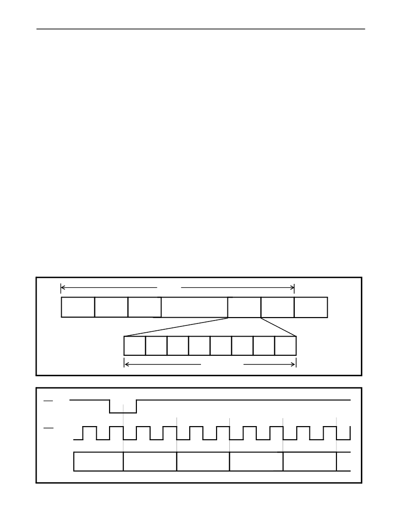
Figure 11 - ST-BUS Stream Format
Figure 12 - Clock & Frame Alignment for ST-BUS Streams
Channel
0
Channel
1
Channel
2
Channel
30
Channel
31
Channel
0
Bit 7
Bit 6
Bit 5
Bit 4
Bit 3
Bit 2
Bit 1
Bit 0
(8/2048) ms
125
μ
s
F0b
C4b
ST-BUS
BIT CELLS
Channel 31
Bit 0
Channel 0
Bit 7
Channel 0
Bit 6
Channel 0
Bit 5
Channel 0
Bit 4
相關(guān)PDF資料 |
PDF描述 |
|---|---|
| MT8931CP | CMOS ST-BUS⑩ FAMILY Subscriber Network Interface Circuit |
| MT8941 | Advanced T1/CEPT Digital Trunk PLL |
| MT8941BE | Advanced T1/CEPT Digital Trunk PLL |
| MT8941BP | Advanced T1/CEPT Digital Trunk PLL |
| MT8941BP1 | Advanced T1/CEPT Digital Trunk PLL |
相關(guān)代理商/技術(shù)參數(shù) |
參數(shù)描述 |
|---|---|
| MT8931CE | 制造商:ZARLINK 制造商全稱:Zarlink Semiconductor Inc 功能描述:Subscriber Network Interface Circuit |
| MT8931CP | 制造商:ZARLINK 制造商全稱:Zarlink Semiconductor Inc 功能描述:Subscriber Network Interface Circuit |
| MT8940 | 制造商:MITEL 制造商全稱:Mitel Networks Corporation 功能描述:ISO-CMOS ST-BUS⑩ FAMILY T1/CEPT Digital Trunk PLL |
| MT8940-1 | 制造商:MITEL 制造商全稱:Mitel Networks Corporation 功能描述:ISO-CMOS ST-BUS⑩ FAMILY T1/CEPT Digital Trunk PLL |
| MT8940AC | 制造商:MITEL 制造商全稱:Mitel Networks Corporation 功能描述:T1/CEPT Digital Trunk PLL |
發(fā)布緊急采購,3分鐘左右您將得到回復。