- 您現(xiàn)在的位置:買賣IC網(wǎng) > PDF目錄359200 > MPXM2051G (飛思卡爾半導(dǎo)體(中國(guó))有限公司) 50 kPa On-Chip Temperature Compensated and Calibrated Silicon Pressure Sensors PDF資料下載
參數(shù)資料
| 型號(hào): | MPXM2051G |
| 廠商: | 飛思卡爾半導(dǎo)體(中國(guó))有限公司 |
| 英文描述: | 50 kPa On-Chip Temperature Compensated and Calibrated Silicon Pressure Sensors |
| 中文描述: | 50千帕片上溫度補(bǔ)償和校準(zhǔn)硅壓力傳感器 |
| 文件頁數(shù): | 2/6頁 |
| 文件大?。?/td> | 217K |
| 代理商: | MPXM2051G |

MPXM2051G
Sensors
2
Freescale Semiconductor
VOLTAGE OUTPUT VERSUS APPLIED DIFFERENTIAL
PRESSURE
The differential voltage output of the sensor is directly
proportional to the differential pressure applied.
The output voltage of the differential or gauge sensor
increases with increasing pressure applied to the pressure
side relative to the vacuum side. Similarly, output voltage
increases as increasing vacuum is applied to the vacuum
side relative to the pressure side.
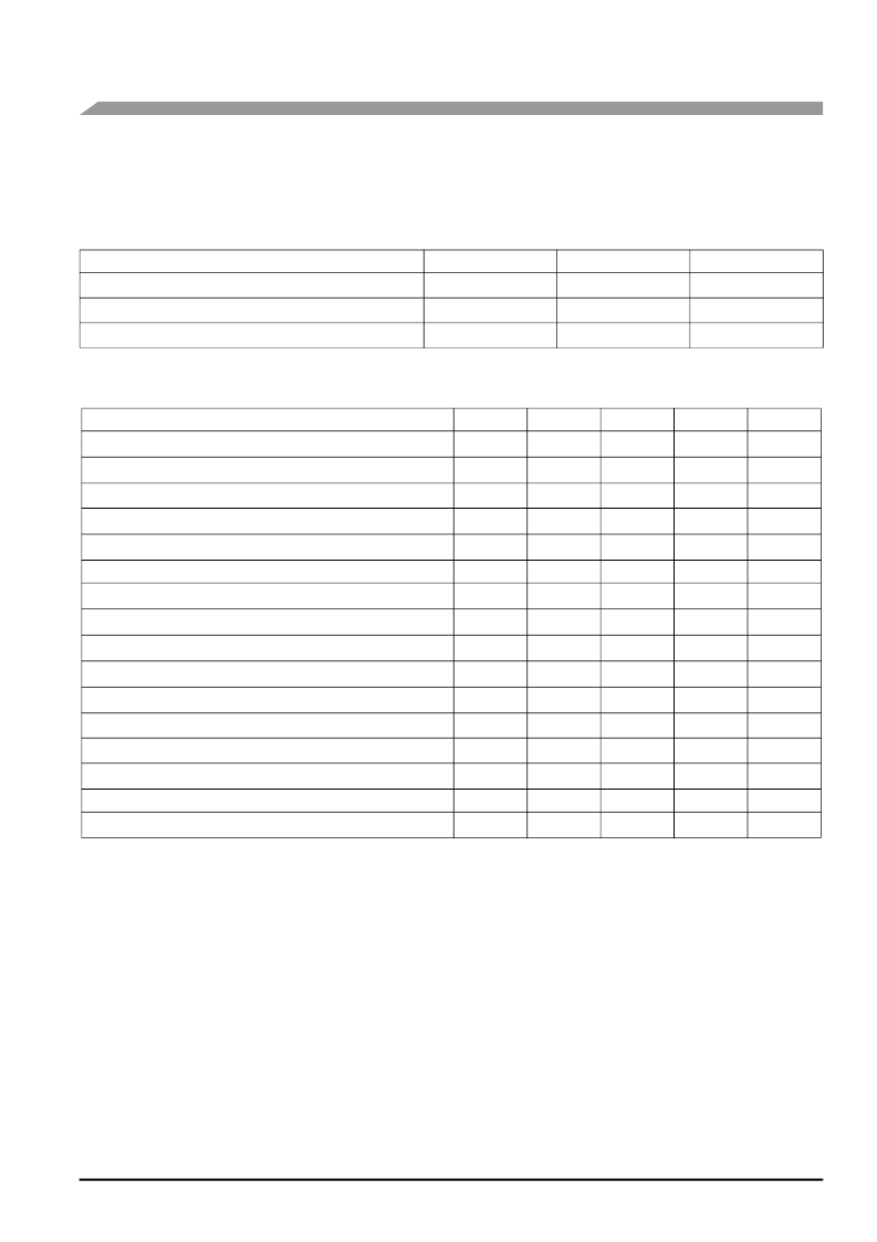
Table 1. Maximum Ratings
(1)
1. Exposure beyond the specified limits may cause permanent damage or degradation to the device.
Rating
Symbol
Value
Unit
Maximum Pressure
P
max
200
kPa
Storage Temperature
T
stg
-40 to +125
°
C
Operating Temperature
T
A
-40 to +125
°
C
Table 2. Operating Characteristics
(V
S
= 10 Vdc, T
A
= 25
°
C.)
Characteristic
Symbol
Min
Typ
Max
Unit
Pressure Range
(1)
1. 1.0 kPa (kiloPascal) equals 0.145 psi.
2. Device is ratiometric within this specified excitation range. Operating the device above the specified excitation range may induce additional
error due to device self-heating.
3. Full Scale Span (V
) is defined as the algebraic difference between the output voltage at full rated pressure and the output voltage at the
minimum rated pressure.
4. Offset (V
off
) is defined as the output voltage at the minimum rated pressure.
5. Accuracy (error budget) consists of the following:
Linearity:
Output deviation from a straight line relationship with pressure, using end point method, over the specified
pressure range.
Τ
emperature Hysteresis: Output deviation at any temperature within the operating temperature range, after the temperature is cycled to
and from the minimum or maximum operating temperature points, with zero differential pressure applied.
Pressure Hysteresis:
Output deviation at any pressure within the specified range, when this pressure is cycled to and from the
minimum or maximum rated pressure, at 25
°
C.
TcSpan:
Output deviation at full rated pressure over the temperature range of 0 to 85
°
C, relative to 25
°
C.
TcOffset:
Output deviation with minimum rated pressure applied, over the temperature range of 0 to 85
°
C, relative
to 25
°
C.
6. Response Time is defined as the time for the incremental change in the output to go from 10% to 90% of its final value when subjected to
a specified step change in pressure.
7. Offset stability is the product's output deviation when subjected to 1000 hours of Pulsed Pressure, Temperature Cycling with Bias Test.
P
OP
0
—
50
kPa
Supply Voltage
(2)
V
S
—
10
16
Vdc
Supply Current
I
o
—
6.0
—
mAdc
Full Scale Span
(3)
V
FSS
38.5
40
41.5
mV
Offset
(4)
V
off
-1.0
—
1.0
mV
Sensitivity
V/
P
—
0.8
—
mV/kPa
Linearity
(5)
—
-0.3
—
0.3
%V
FSS
Pressure Hysteresis
(5)
(0 to 50 kPa)
—
—
±
0.1
—
%V
FSS
Temperature Hysteresis
(5)
(-40
°
C to +125
°
C)
—
—
±
0.5
—
%V
FSS
Temperature Effect on Full Scale Span
(5)
TCV
FSS
-1.0
—
1.0
%V
FSS
Temperature Effect on Offset
(5)
TCV
off
-1.0
—
1.0
mV
Input Impedance
Z
in
1000
—
2500
Output Impedance
Z
out
1400
—
3000
Response Time
(6)
(10% to 90%)
t
R
—
1.0
—
ms
Warm-Up
—
—
20
—
ms
Offset Stability
(7)
—
—
±
0.5
—
%V
FSS
相關(guān)PDF資料 |
PDF描述 |
|---|---|
| MPXM2053D | 50kPa On-Chip Temperature Compensated & Calibrated Silicon Pressure Sensors(50kPa片內(nèi)溫度補(bǔ)償和校準(zhǔn)硅壓力傳感器) |
| MPXM2053GST1 | 50 kPa On-Chip Temperature Compensated & Calibrated Silicon Pressure Sensors |
| MPXM2053D | Sensor |
| MPXM2053DT1 | Sensor |
| MPXM2053GS | Sensor |
相關(guān)代理商/技術(shù)參數(shù) |
參數(shù)描述 |
|---|---|
| MPXM2051G_09 | 制造商:FREESCALE 制造商全稱:Freescale Semiconductor, Inc 功能描述:50 kPa On-Chip Temperature Compensated and Calibrated Silicon Pressure Sensors |
| MPXM2051GS | 功能描述:板上安裝壓力/力傳感器 M-PAK PORTED RoHS:否 制造商:Honeywell 工作壓力:0 bar to 4 bar 壓力類型:Gage 準(zhǔn)確性:+ / - 0.25 % 輸出類型:Digital 安裝風(fēng)格:Through Hole 工作電源電壓:5 V 封裝 / 箱體:SIP 端口類型:Dual Radial Barbed, Same sides |
| MPXM2051GST1 | 功能描述:板上安裝壓力/力傳感器 M-PAK PORTED RoHS:否 制造商:Honeywell 工作壓力:0 bar to 4 bar 壓力類型:Gage 準(zhǔn)確性:+ / - 0.25 % 輸出類型:Digital 安裝風(fēng)格:Through Hole 工作電源電壓:5 V 封裝 / 箱體:SIP 端口類型:Dual Radial Barbed, Same sides |
| MPXM2053 | 制造商:FREESCALE 制造商全稱:Freescale Semiconductor, Inc 功能描述:50 kPa On-Chip Temperature Compensated and Calibrated Silicon Pressure Sensors |
| MPXM2053_06 | 制造商:FREESCALE 制造商全稱:Freescale Semiconductor, Inc 功能描述:50 kPa On-Chip Temperature Compensated and Calibrated Silicon Pressure Sensors |
發(fā)布緊急采購(gòu),3分鐘左右您將得到回復(fù)。