- 您現(xiàn)在的位置:買賣IC網(wǎng) > PDF目錄45341 > MPC5604PFF0VLL6 (FREESCALE SEMICONDUCTOR INC) 32-BIT, FLASH, 64 MHz, MICROCONTROLLER, PQFP100 PDF資料下載
參數(shù)資料
| 型號(hào): | MPC5604PFF0VLL6 |
| 廠商: | FREESCALE SEMICONDUCTOR INC |
| 元件分類: | 微控制器/微處理器 |
| 英文描述: | 32-BIT, FLASH, 64 MHz, MICROCONTROLLER, PQFP100 |
| 封裝: | 14 X 14 MM, 1.40 MM HEIGHT, 0.50 MM PITCH, ROHS COMPLIANT LQFP-100 |
| 文件頁(yè)數(shù): | 68/99頁(yè) |
| 文件大小: | 1130K |
| 代理商: | MPC5604PFF0VLL6 |
第1頁(yè)第2頁(yè)第3頁(yè)第4頁(yè)第5頁(yè)第6頁(yè)第7頁(yè)第8頁(yè)第9頁(yè)第10頁(yè)第11頁(yè)第12頁(yè)第13頁(yè)第14頁(yè)第15頁(yè)第16頁(yè)第17頁(yè)第18頁(yè)第19頁(yè)第20頁(yè)第21頁(yè)第22頁(yè)第23頁(yè)第24頁(yè)第25頁(yè)第26頁(yè)第27頁(yè)第28頁(yè)第29頁(yè)第30頁(yè)第31頁(yè)第32頁(yè)第33頁(yè)第34頁(yè)第35頁(yè)第36頁(yè)第37頁(yè)第38頁(yè)第39頁(yè)第40頁(yè)第41頁(yè)第42頁(yè)第43頁(yè)第44頁(yè)第45頁(yè)第46頁(yè)第47頁(yè)第48頁(yè)第49頁(yè)第50頁(yè)第51頁(yè)第52頁(yè)第53頁(yè)第54頁(yè)第55頁(yè)第56頁(yè)第57頁(yè)第58頁(yè)第59頁(yè)第60頁(yè)第61頁(yè)第62頁(yè)第63頁(yè)第64頁(yè)第65頁(yè)第66頁(yè)第67頁(yè)當(dāng)前第68頁(yè)第69頁(yè)第70頁(yè)第71頁(yè)第72頁(yè)第73頁(yè)第74頁(yè)第75頁(yè)第76頁(yè)第77頁(yè)第78頁(yè)第79頁(yè)第80頁(yè)第81頁(yè)第82頁(yè)第83頁(yè)第84頁(yè)第85頁(yè)第86頁(yè)第87頁(yè)第88頁(yè)第89頁(yè)第90頁(yè)第91頁(yè)第92頁(yè)第93頁(yè)第94頁(yè)第95頁(yè)第96頁(yè)第97頁(yè)第98頁(yè)第99頁(yè)

MPC5604P Microcontroller Data Sheet, Rev. 7
Freescale Semiconductor
70
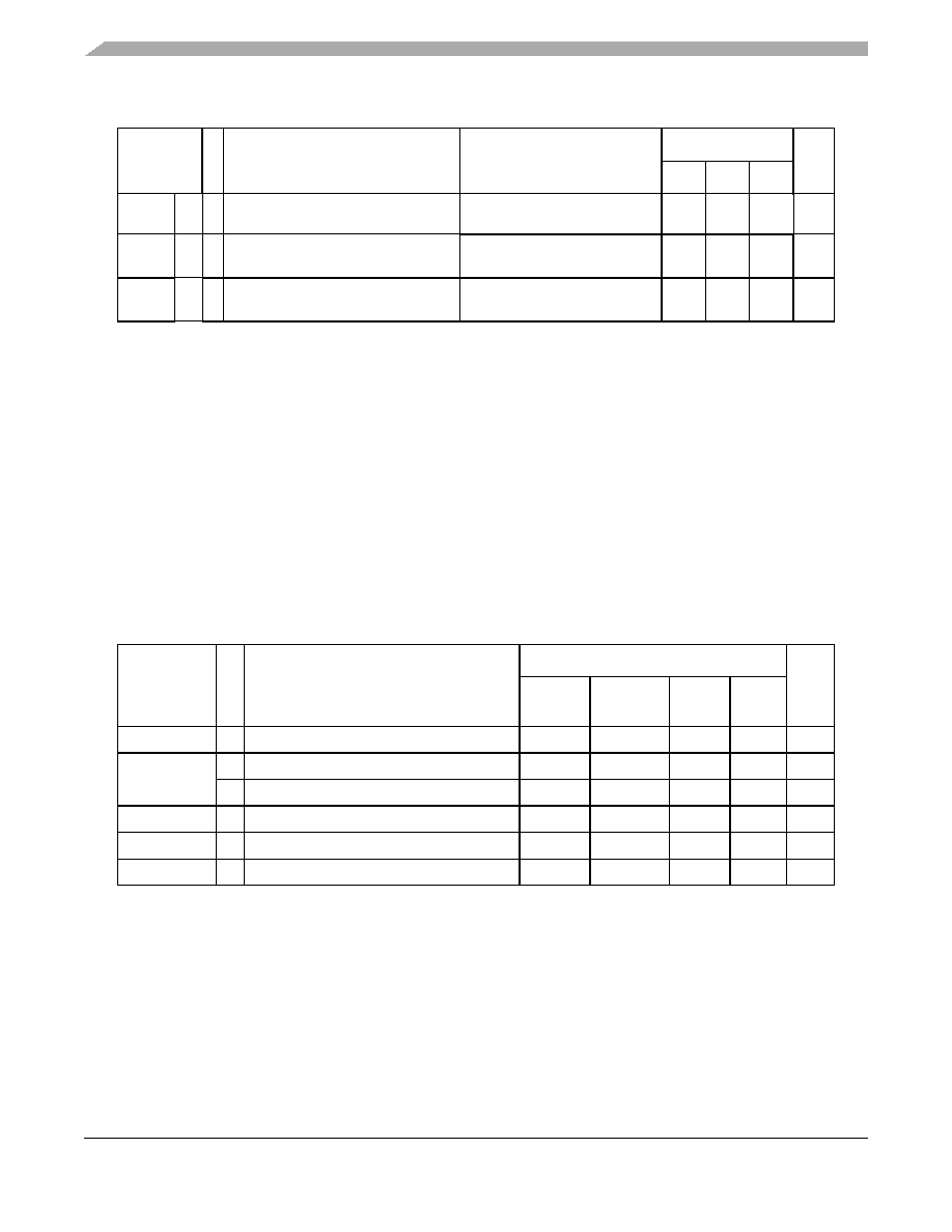
3.15
Flash memory electrical characteristics
GE
CC T Gain error
—
±1
—
LSB
TUE
CC P Total unadjusted error without current
injection
—–2.5
—
2.5
LSB
TUE
CC T Total unadjusted error with current
injection
—–3
—
3
LSB
1 V
DD = 3.3 V to 3.6 V / 4.5 V to 5.5 V, TA = –40 °C to TA MAX, unless otherwise specified and analog input voltage
from VSS_HV_ADCx to VDD_HV_ADCx.
2 AD_clk clock is always half of the ADC module input clock defined via the auxiliary clock divider for the ADC.
3 When configured to allow 60 MHz ADC, the minimum ADC clock speed is 9 MHz, below which precision is lost.
4 During the sample time the input capacitance CS can be charged/discharged by the external source. The internal
resistance of the analog source must allow the capacitance to reach its final voltage level within tADC_S. After the
end of the sample time tADC_S, changes of the analog input voltage have no effect on the conversion result. Values
for the sample clock tADC_S depend on programming.
5 This parameter includes the sample time t
ADC_S.
6 20 MHz ADC clock. Specific prescaler is programmed on MC_PLL_CLK to provide 20 MHz clock to the ADC.
7 See Figure 15.
Table 31. Program and erase specifications
Symbol
C
Parameter
Value
Unit
Min
Typical1
1 Typical program and erase times assume nominal supply values and operation at 25 °C. All times are subject to
change pending device characterization.
Initial
max2
2 Initial factory condition: < 100 program/erase cycles, 25 °C, typical supply voltage.
Max3
3 The maximum program and erase times occur after the specified number of program/erase cycles. These maximum
values are characterized but not guaranteed.
Tdwprogram
P Double Word (64 bits) Program Time4
4 Actual hardware programming times. This does not include software overhead.
—
22
50
500
s
TBKPRG
P Bank Program (512 KB)4, 5
5 Typical Bank programming time assumes that all cells are programmed in a single pulse. In reality some cells will
require more than one pulse, adding a small overhead to total bank programming time (see Initial Max column).
—
1.45
1.65
33
s
P Bank Program (64 KB)4, 5
—
0.18
0.21
4.10
s
T16kpperase
P 16 KB Block Pre-program and Erase Time
—
300
500
5000
ms
T32kpperase
P 32 KB Block Pre-program and Erase Time
—
400
600
5000
ms
T128kpperase
P 128 KB Block Pre-program and Erase Time
—
800
1300
7500
ms
Table 30. ADC conversion characteristics (continued)
Symbol
C
Parameter
Conditions1
Value
Unit
Min
Typ
Max
相關(guān)PDF資料 |
PDF描述 |
|---|---|
| MPC5604PGF0VLL4 | 32-BIT, FLASH, 40 MHz, MICROCONTROLLER, PQFP100 |
| MPC5604PFF0MLL4 | 32-BIT, FLASH, 40 MHz, MICROCONTROLLER, PQFP100 |
| MPC5604PEF0VLQ6 | 32-BIT, FLASH, 64 MHz, MICROCONTROLLER, PQFP144 |
| MPC5604PGF0MLQ6R | 32-BIT, FLASH, 64 MHz, MICROCONTROLLER, PQFP144 |
| MPC5604PEF0VLL4 | 32-BIT, FLASH, 40 MHz, MICROCONTROLLER, PQFP100 |
相關(guān)代理商/技術(shù)參數(shù) |
參數(shù)描述 |
|---|---|
| MPC5604PFF0VLL7R | 制造商:FREESCALE 制造商全稱:Freescale Semiconductor, Inc 功能描述:microcontroller units (MCUs) |
| MPC5604PFF0VLQ7R | 制造商:FREESCALE 制造商全稱:Freescale Semiconductor, Inc 功能描述:microcontroller units (MCUs) |
| MPC5604S | 制造商:FREESCALE 制造商全稱:Freescale Semiconductor, Inc 功能描述:MPC5606S Microcontroller Data Sheet |
| MPC5605B | 制造商:FREESCALE 制造商全稱:Freescale Semiconductor, Inc 功能描述:Qorivva MPC560xB/C/D Family |
| MPC5605BECLLR | 制造商:FREESCALE 制造商全稱:Freescale Semiconductor, Inc 功能描述:Microcontroller |
發(fā)布緊急采購(gòu),3分鐘左右您將得到回復(fù)。