- 您現(xiàn)在的位置:買(mǎi)賣(mài)IC網(wǎng) > PDF目錄45341 > MPC5604BF1MLL4R (FREESCALE SEMICONDUCTOR INC) MICROCONTROLLER, PQFP100 PDF資料下載
參數(shù)資料
| 型號(hào): | MPC5604BF1MLL4R |
| 廠商: | FREESCALE SEMICONDUCTOR INC |
| 元件分類(lèi): | 微控制器/微處理器 |
| 英文描述: | MICROCONTROLLER, PQFP100 |
| 封裝: | 14 X 14 MM, 1.40 MM HEIGHT, 0.50 MM PITCH, LQFP-100 |
| 文件頁(yè)數(shù): | 57/104頁(yè) |
| 文件大小: | 953K |
| 代理商: | MPC5604BF1MLL4R |
第1頁(yè)第2頁(yè)第3頁(yè)第4頁(yè)第5頁(yè)第6頁(yè)第7頁(yè)第8頁(yè)第9頁(yè)第10頁(yè)第11頁(yè)第12頁(yè)第13頁(yè)第14頁(yè)第15頁(yè)第16頁(yè)第17頁(yè)第18頁(yè)第19頁(yè)第20頁(yè)第21頁(yè)第22頁(yè)第23頁(yè)第24頁(yè)第25頁(yè)第26頁(yè)第27頁(yè)第28頁(yè)第29頁(yè)第30頁(yè)第31頁(yè)第32頁(yè)第33頁(yè)第34頁(yè)第35頁(yè)第36頁(yè)第37頁(yè)第38頁(yè)第39頁(yè)第40頁(yè)第41頁(yè)第42頁(yè)第43頁(yè)第44頁(yè)第45頁(yè)第46頁(yè)第47頁(yè)第48頁(yè)第49頁(yè)第50頁(yè)第51頁(yè)第52頁(yè)第53頁(yè)第54頁(yè)第55頁(yè)第56頁(yè)當(dāng)前第57頁(yè)第58頁(yè)第59頁(yè)第60頁(yè)第61頁(yè)第62頁(yè)第63頁(yè)第64頁(yè)第65頁(yè)第66頁(yè)第67頁(yè)第68頁(yè)第69頁(yè)第70頁(yè)第71頁(yè)第72頁(yè)第73頁(yè)第74頁(yè)第75頁(yè)第76頁(yè)第77頁(yè)第78頁(yè)第79頁(yè)第80頁(yè)第81頁(yè)第82頁(yè)第83頁(yè)第84頁(yè)第85頁(yè)第86頁(yè)第87頁(yè)第88頁(yè)第89頁(yè)第90頁(yè)第91頁(yè)第92頁(yè)第93頁(yè)第94頁(yè)第95頁(yè)第96頁(yè)第97頁(yè)第98頁(yè)第99頁(yè)第100頁(yè)第101頁(yè)第102頁(yè)第103頁(yè)第104頁(yè)

MPC5604B/C Microcontroller Data Sheet, Rev. 9
Electrical characteristics
Freescale Semiconductor
56
ECC circuitry provides correction of single bit faults and is used to improve further automotive reliability results. Some units
will experience single bit corrections throughout the life of the product with no impact to product reliability.
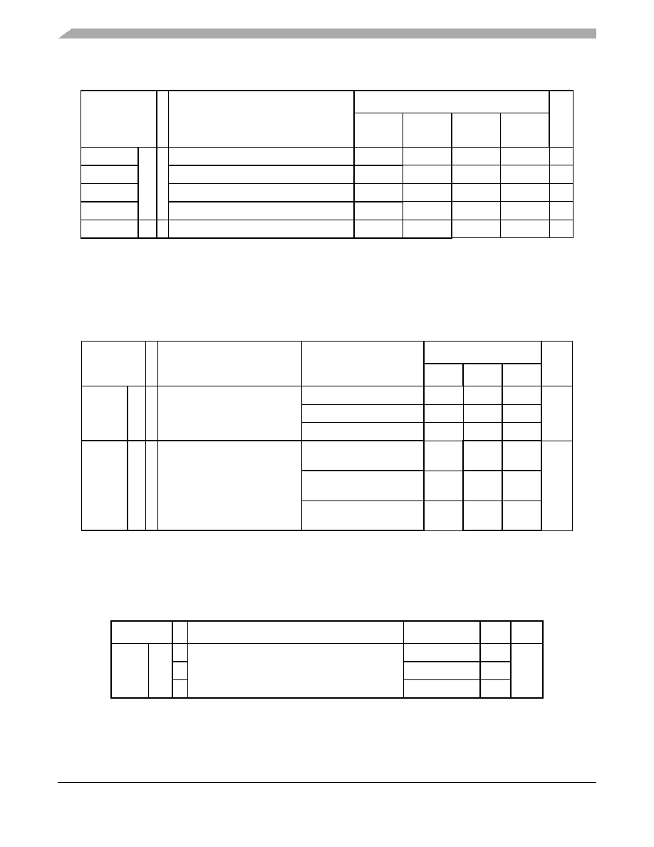
Table 28. Program and erase specifications
Symbol
C
Parameter
Value
Unit
Min
Typ1
1 Typical program and erase times assume nominal supply values and operation at 25 °C.
Initial
max2
2 Initial factory condition: < 100 program/erase cycles, 25 °C, typical supply voltage.
Max3
3 The maximum program and erase times occur after the specified number of program/erase cycles. These maximum
values are characterized but not guaranteed.
Tdwprogram CC C Double word (64 bits) program time
4
4 Actual hardware programming times. This does not include software overhead.
—22
50
500
s
T16Kpperase
16 KB block preprogram and erase time
—
300
500
5000
ms
T32Kpperase
32 KB block preprogram and erase time
—
400
600
5000
ms
T128Kpperase
128 KB block preprogram and erase time
—
800
1300
7500
ms
Tesus
CC D Erase suspend latency
—
30
s
Table 29. Flash module life
Symbol
C
Parameter
Conditions
Value
Unit
Min
Typ
Max
P/E
CC C Number of program/erase cycles
per block over the operating
temperature range (TJ)
16 KB blocks
100,000
—
cycles
32 KB blocks
10,000 100,000
—
128 KB blocks
1,000
100,000
—
Retention CC C Minimum data retention at 85 °C
average ambient temperature1
1 Ambient temperature averaged over duration of application, not to exceed recommended product operating
temperature range.
Blocks with
0–1,000 P/E cycles
20
—
years
Blocks with
1,001–10,000 P/E cycles
10
—
Blocks with
10,001–100,000 P/E cycles
5—
—
Table 30. Flash read access timing
Symbol
C
Parameter
Conditions1
1 V
DD = 3.3 V ± 10% / 5.0 V ± 10%, TA = 40 to 125 °C, unless otherwise specified
Max
Unit
fREAD
CC
P Maximum frequency for Flash reading
2 wait states
64
MHz
C
1 wait state
40
C
0 wait states
20
相關(guān)PDF資料 |
PDF描述 |
|---|---|
| MPC5604CF1MLH4R | MICROCONTROLLER, PQFP64 |
| MPC5604CF1MLH4 | MICROCONTROLLER, PQFP64 |
| MPC5604BF1VLH4 | MICROCONTROLLER, PQFP64 |
| MPC5604CF1MLL6 | MICROCONTROLLER, PQFP100 |
| MPC5604BF1VMG6 | MICROCONTROLLER, PBGA208 |
相關(guān)代理商/技術(shù)參數(shù) |
參數(shù)描述 |
|---|---|
| MPC5604BF1MLL6 | 制造商:Freescale Semiconductor 功能描述:MPC5604BF1MLL6 - Bulk |
| MPC5604BF1MLL6R | 制造商:Freescale Semiconductor 功能描述:MPC5604BF1MLL6R - Tape and Reel |
| MPC5604BF1MLQ6 | 制造商:Freescale Semiconductor 功能描述:MPC5604BF1MLQ6 - Bulk 制造商:Freescale Semiconductor 功能描述:MCU 32BIT 512KB FLASH 144LQ |
| MPC5604BF1MLQ6R | 制造商:Freescale Semiconductor 功能描述:MPC5604BF1MLQ6R - Tape and Reel |
| MPC5604BMLL4R | 制造商:FREESCALE 制造商全稱:Freescale Semiconductor, Inc 功能描述:MPC5604B/C Microcontroller |
發(fā)布緊急采購(gòu),3分鐘左右您將得到回復(fù)。