- 您現(xiàn)在的位置:買賣IC網(wǎng) > PDF目錄369919 > MLVS0603K11 (Electronic Theatre Controls, Inc.) This specification is applicable to Chip Metal Oxide Varistor in multilayer technology PDF資料下載
參數(shù)資料
| 型號: | MLVS0603K11 |
| 廠商: | Electronic Theatre Controls, Inc. |
| 英文描述: | This specification is applicable to Chip Metal Oxide Varistor in multilayer technology |
| 中文描述: | 本規(guī)范適用于金屬氧化物壓敏電阻片的多層技術 |
| 文件頁數(shù): | 1/1頁 |
| 文件大?。?/td> | 56K |
| 代理商: | MLVS0603K11 |

MLV S S eries
MLVS-0603 Series
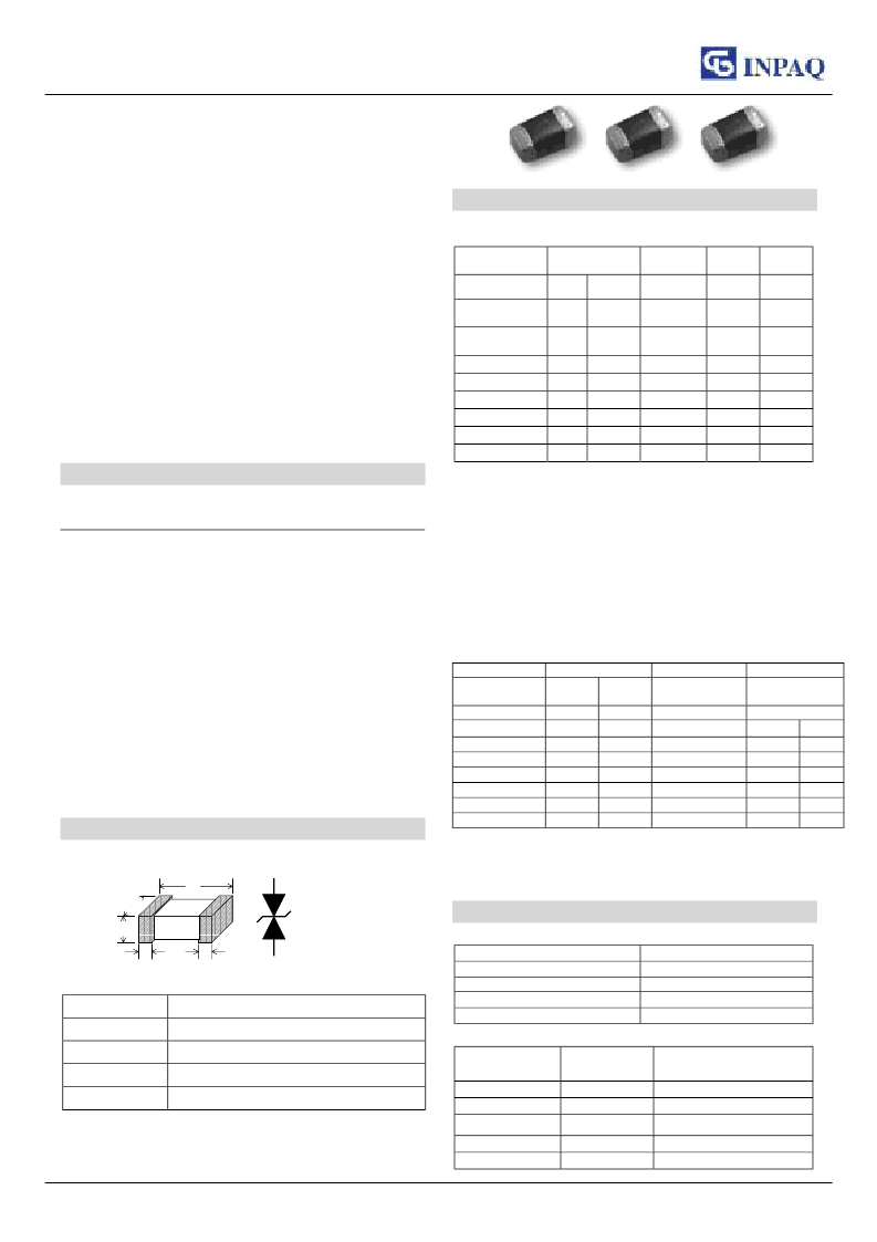
This specification is applicable to Chip Metal
Oxide Varistor in multilayer technology.
Features
1. Keeping low and stable leakage current.
2. Excellent assembly solderability.
3. Low clamping Voltage.
4. Quick response time (<1nSec.)
5. High transient current capability
6. Test Standard meets IEC 61000-4-2, 61000-4-4,
and 61000-4-5.
Part Number
SeriesType
MLV
MLV
MLV
MLV
MLV
MLV
Elements
S
S
S
S
S
S
Size
0603
0603
0603
0603
0603
0603
Tolerance
M
M
M
L
K
K
Vrms
04
06
07
08
11
14
z
Series Type / MLV — Multilayer Varistor
z
Elements / S — Single
z
Size /0603 —1.60x0.80x0.80mm
3
z
Tolerance /M/L/K — 20%/ 15%/
z
Vrms — Working Voltage Vrms
Dimensions
L
W
T
C
Unit : mm
INPAQ TECHNOLOGY CO.,LTD
10%
C
0603
1.60 0.20
0.80 0.20
0.80 0.20
0.30 0.20
Specifications
1.Rating(25 5
)
Working voltage Resistance
Peak
current
i
max
Amps
(Max.)
Transient
energy
W
max
Joules
(Max.)
10/1000
μ
s
0.1
0.1
0.1
0.1
0.1
0.1
Symbol
V
RMS
V
DC
Volts
(Max.)
Ir
Units
Volts
X10
6
ohm
(Min.)
Test Condition
< 10
μ
A
5 VDC
10
*
10
*
10
*
10
10
10
8/20
μ
s
MLVS0603M04
MLVS0603M06
MLVS0603M07
MLVS0603L08
MLVS0603K11
MLVS0603K14
z
*Measured resistance at 3.3V DC
z
V
RMS
– Maximum AC operating voltage the varistor can maintain and not
exceed 10
μ
A leakage current
z
V
DC
– Maximum DC operating voltage the varistor can maintain and not
exceed 10
μ
A leakage current
z
Ir – Resistance at 5 V DC
z
i
max
– Maximum peak current which may be applied with 8/20us
waveform without device failure
z
W
max
– Maximum energy which may be dissipated with
the 10/1000us waveform without device failure
4
6
7
8
11
14
5.5
8
9
11
14
18
30
30
30
30
30
30
2.Characteristics(25
5
)
Clamping Voltage
Varistor voltage
Capacitance
Symbol
V
V
V
V
Vc
Cp
Units
Test Condition
MLVS0603M04
MLVS0603M06
MLVS0603M07
MLVS0603L08
MLVS0603K11
MLVS0603K14
z
V
V
– Voltage across the device measured at 1mA DC current
z
Vc – Maximum peak current across the varistor with 8/20us waveform and 1A
pulse current
z
Cp – Device capacitance measured with zero volt bias 1Vrms
Volts
1mA DC
8
11
12.5
15
18
22
%
±
20
±
20
±
20
±
15
±
10
±
10
Volt (Max.)
1A 8/20
μ
s
19
27
27
33
35
40
pF (typ.)
1KHz
300
250
235
220
160
140
1MHz
270
230
205
190
140
120
C
L
T
W
Electrical Characteristics
1.General technical Characteristics
Operating temperature
Storage temperature
esponse time
Solderability
Solder leach resistance
2. Environmental Characteristics
-55 … +125
-55 … +125
<1 ns
235
260
(85
(85
)
)
, 2s
, 10s
Characteristics
Specifications
Test condition
Bias humidity
Thermal shock
Vibration
Full load voltage
Solder leach resistance
V
V
/V
V
V
V
/V
V
V
V
/V
V
V
V
/V
V
V
V
/V
V
±10%
90%RH, 40 , Working voltage, 1000 hours
±10%
-40
to 85
, 30 min. cycle, 5 cycles
±10%
X-Y-Z
±10%
Working voltage, 25
±10%
260
, 10s
10 to 50 to 10 Hz, 1 min. cycle, 2 hours each in
, 1000 hours
相關PDF資料 |
PDF描述 |
|---|---|
| MLVS0603K14 | This specification is applicable to Chip Metal Oxide Varistor in multilayer technology |
| MLVS0603L08 | This specification is applicable to Chip Metal Oxide Varistor in multilayer technology |
| MLVS0603M04 | This specification is applicable to Chip Metal Oxide Varistor in multilayer technology |
| MLVS0603M06 | This specification is applicable to Chip Metal Oxide Varistor in multilayer technology |
| MLVS0603M07 | This specification is applicable to Chip Metal Oxide Varistor in multilayer technology |
相關代理商/技術參數(shù) |
參數(shù)描述 |
|---|---|
| MLVS0603K14 | 制造商: 功能描述:Multilayer Varistor 制造商:undefined 功能描述:Multilayer Varistor |
| MLVS0603K20 | 制造商:undefined 功能描述:Multilayer Varistor |
| MLVS0603L08 | 制造商:未知廠家 制造商全稱:未知廠家 功能描述:This specification is applicable to Chip Metal Oxide Varistor in multilayer technology |
| MLVS0603M04 | 制造商:undefined 功能描述:Multilayer Varistor |
| MLVS0603M06 | 制造商:未知廠家 制造商全稱:未知廠家 功能描述:This specification is applicable to Chip Metal Oxide Varistor in multilayer technology |
發(fā)布緊急采購,3分鐘左右您將得到回復。