- 您現(xiàn)在的位置:買賣IC網(wǎng) > PDF目錄67987 > MCV14AT-I/SL 8-BIT, FLASH, 20 MHz, RISC MICROCONTROLLER, PDSO14 PDF資料下載
參數(shù)資料
| 型號: | MCV14AT-I/SL |
| 元件分類: | 微控制器/微處理器 |
| 英文描述: | 8-BIT, FLASH, 20 MHz, RISC MICROCONTROLLER, PDSO14 |
| 封裝: | 3.90 MM, PLASTIC, SOIC-14 |
| 文件頁數(shù): | 18/82頁 |
| 文件大小: | 1053K |
| 代理商: | MCV14AT-I/SL |
第1頁第2頁第3頁第4頁第5頁第6頁第7頁第8頁第9頁第10頁第11頁第12頁第13頁第14頁第15頁第16頁第17頁當(dāng)前第18頁第19頁第20頁第21頁第22頁第23頁第24頁第25頁第26頁第27頁第28頁第29頁第30頁第31頁第32頁第33頁第34頁第35頁第36頁第37頁第38頁第39頁第40頁第41頁第42頁第43頁第44頁第45頁第46頁第47頁第48頁第49頁第50頁第51頁第52頁第53頁第54頁第55頁第56頁第57頁第58頁第59頁第60頁第61頁第62頁第63頁第64頁第65頁第66頁第67頁第68頁第69頁第70頁第71頁第72頁第73頁第74頁第75頁第76頁第77頁第78頁第79頁第80頁第81頁第82頁
2009 Microchip Technology Inc.
Preliminary
DS41338C-page 25
MCV14A
5.0
I/O PORT
As with any other register, the I/O register(s) can be
written and read under program control. However, read
instructions (e.g., MOVF PORTB,W) always read the I/O
pins independent of the pin’s Input/Output modes. On
Reset, all I/O ports are defined as input (inputs are at high-
impedance) since the I/O control registers are all set.
5.1
PORTB
PORTB is a 6-bit I/O register. Only the low-order 6 bits
are used (RB<5:0>). Bits 7 and 6 are unimplemented
and read as ‘0’s. Please note that RB3 is an input only
pin. The Configuration Word can set several I/O’s to
alternate functions. When acting as alternate functions,
the pins will read as ‘0’ during a port read. Pins RB0,
RB1, RB3 and RB4 can be configured with weak pull-
ups and also for wake-up on change. The wake-up on
change and weak pull-up functions are not pin select-
able. If RB3/MCLR is configured as MCLR, weak pull-
up is always on and wake-up on change for this pin is
not enabled.
5.2
PORTC
PORTC is a 6-bit I/O register. Only the low-order 6 bits
are used (RC<5:0>). Bits 7 and 6 are unimplemented
and read as ‘0’s.
5.3
TRIS Register
The Output Driver Control register is loaded with the
contents of the W register by executing the TRIS f
instruction. A ‘1’ from a TRIS register bit puts the corre-
sponding output driver in a High-Impedance mode. A
‘0’ puts the contents of the output data latch on the
selected pins, enabling the output buffer. The excep-
tions are RB3, which is input only and the T0CKI pin,
which may be controlled by the OPTION register. See
Register 3-2 and Register 3-3.
The TRIS register is “write-only” and is set (output
drivers disabled) upon Reset.
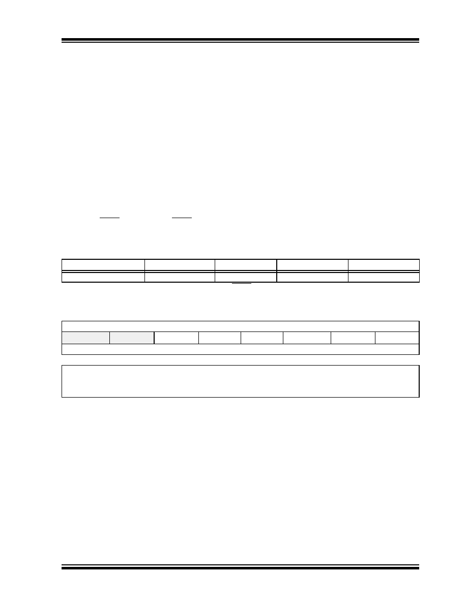
TABLE 5-1:
WEAK PULL-UP ENABLED PINS
Device
RB0 Weak Pull-up
RB1 Weak Pull-up RB3 Weak Pull-up(1)
RB4 Weak Pull-up
MCV14A
Yes
Note 1: When MCLREN = 1, the weak pull-up on RB3/MCLR is always enabled.
REGISTER 5-1:
PORTB: PORTB REGISTER
U-0
R/W-x
—
RB5
RB4
RB3
RB2
RB1
RB0
bit 7
bit 0
Legend:
R = Readable bit
W = Writable bit
U = Unimplemented bit, read as ‘0’
-n = Value at POR
‘1’ = Bit is set
‘0’ = Bit is cleared
x = Bit is unknown
bit 7-6
Unimplemented: Read as ‘1’
bit 5-0
RB<5:0>: PORTB I/O Pin bits
1
= Port pin is >VIH min.
0
= Port pin is <VIL max.
相關(guān)PDF資料 |
PDF描述 |
|---|---|
| MCV14A-I/SL | 8-BIT, FLASH, 20 MHz, RISC MICROCONTROLLER, PDSO14 |
| MCV18ET-I/SO | FLASH, 20 MHz, RISC MICROCONTROLLER, PDSO18 |
| MCV18E-I/P | 32-BIT, FLASH, 20 MHz, RISC MICROCONTROLLER, PDIP18 |
| MD8086-2/B | 16-BIT, 8 MHz, MICROPROCESSOR, CDIP40 |
| MD80C154-12/883D | 8-BIT, 12 MHz, MICROCONTROLLER, CDIP40 |
相關(guān)代理商/技術(shù)參數(shù) |
參數(shù)描述 |
|---|---|
| MCV15/10-GF-381 | 制造商:Phoenix Contact 功能描述:HEADER PCB VERTICAL 3.81MM 10WAY |
| MCV15/2-GF-381 | 制造商:Phoenix Contact 功能描述:HEADER PCB VERTICAL 3.81MM 2WAY |
| MCV15/3-GF-381 | 制造商:Phoenix Contact 功能描述:HEADER PCB VERTICAL 3.81MM 3WAY |
| MCV15/4-GF-381 | 制造商:Phoenix Contact 功能描述:HEADER PCB VERTICAL 3.81MM 4WAY |
| MCV15/5-GF-381 | 制造商:Phoenix Contact 功能描述:HEADER PCB VERTICAL 3.81MM 5WAY |
發(fā)布緊急采購,3分鐘左右您將得到回復(fù)。