- 您現(xiàn)在的位置:買賣IC網(wǎng) > PDF目錄11599 > MCP2510-I/SO (Microchip Technology)IC CAN CONTRLER IND TEMP 18SOIC PDF資料下載
參數(shù)資料
| 型號: | MCP2510-I/SO |
| 廠商: | Microchip Technology |
| 文件頁數(shù): | 58/80頁 |
| 文件大?。?/td> | 0K |
| 描述: | IC CAN CONTRLER IND TEMP 18SOIC |
| 產(chǎn)品培訓模塊: | CAN Bus Protection |
| 標準包裝: | 42 |
| 控制器類型: | CAN 接口 |
| 接口: | SPI |
| 電源電壓: | 3 V ~ 5.5 V |
| 電流 - 電源: | 10mA |
| 工作溫度: | -40°C ~ 85°C |
| 安裝類型: | 表面貼裝 |
| 封裝/外殼: | 18-SOIC(0.295",7.50mm 寬) |
| 供應商設備封裝: | 18-SOIC |
| 包裝: | 管件 |
| 產(chǎn)品目錄頁面: | 685 (CN2011-ZH PDF) |
| 配用: | DV251001-ND - KIT DEVELOPMENT CAN MCP2510 |
第1頁第2頁第3頁第4頁第5頁第6頁第7頁第8頁第9頁第10頁第11頁第12頁第13頁第14頁第15頁第16頁第17頁第18頁第19頁第20頁第21頁第22頁第23頁第24頁第25頁第26頁第27頁第28頁第29頁第30頁第31頁第32頁第33頁第34頁第35頁第36頁第37頁第38頁第39頁第40頁第41頁第42頁第43頁第44頁第45頁第46頁第47頁第48頁第49頁第50頁第51頁第52頁第53頁第54頁第55頁第56頁第57頁當前第58頁第59頁第60頁第61頁第62頁第63頁第64頁第65頁第66頁第67頁第68頁第69頁第70頁第71頁第72頁第73頁第74頁第75頁第76頁第77頁第78頁第79頁第80頁
2009 Microchip Technology Inc.
DS39637D-page 61
PIC18F2480/2580/4480/4580
TXB2D6
2480 2580 4480 4580
xxxx xxxx
uuuu uuuu
0uuu uuuu
TXB2D5
2480 2580 4480 4580
xxxx xxxx
uuuu uuuu
0uuu uuuu
TXB2D4
2480 2580 4480 4580
xxxx xxxx
uuuu uuuu
0uuu uuuu
TXB2D3
2480 2580 4480 4580
xxxx xxxx
uuuu uuuu
0uuu uuuu
TXB2D2
2480 2580 4480 4580
xxxx xxxx
uuuu uuuu
0uuu uuuu
TXB2D1
2480 2580 4480 4580
xxxx xxxx
uuuu uuuu
0uuu uuuu
TXB2D0
2480 2580 4480 4580
xxxx xxxx
uuuu uuuu
0uuu uuuu
TXB2DLC
2480 2580 4480 4580
-x-- xxxx
-u-- uuuu
TXB2EIDL
2480 2580 4480 4580
xxxx xxxx
uuuu uuuu
TXB2EIDH
2480 2580 4480 4580
xxxx xxxx
uuuu uuuu
TXB2SIDL
2480 2580 4480 4580
xxxx x-xx
uuuu u-uu
-uuu uuuu
TXB2SIDH
2480 2580 4480 4580
xxx- x-xx
uuu- u-uu
TXB2CON
2480 2580 4480 4580
0000 0-00
uuuu u-uu
RXM1EIDL
2480 2580 4480 4580
xxxx xxxx
uuuu uuuu
RXM1EIDH
2480 2580 4480 4580
xxxx xxxx
uuuu uuuu
RXM1SIDL
2480 2580 4480 4580
xxx- x-xx
uuu- u-uu
RXM1SIDH
2480 2580 4480 4580
xxxx xxxx
uuuu uuuu
RXM0EIDL
2480 2580 4480 4580
xxxx xxxx
uuuu uuuu
RXM0EIDH
2480 2580 4480 4580
xxxx xxxx
uuuu uuuu
RXM0SIDL
2480 2580 4480 4580
xxx- x-xx
uuu- u-uu
RXM0SIDH
2480 2580 4480 4580
xxxx xxxx
uuuu uuuu
RXF5EIDL
2480 2580 4480 4580
xxxx xxxx
uuuu uuuu
RXF5EIDH
2480 2580 4480 4580
xxxx xxxx
uuuu uuuu
RXF5SIDL
2480 2580 4480 4580
xxx- x-xx
uuu- u-uu
RXF5SIDH
2480 2580 4480 4580
xxxx xxxx
uuuu uuuu
RXF4EIDL
2480 2580 4480 4580
xxxx xxxx
uuuu uuuu
RXF4EIDH
2480 2580 4480 4580
xxxx xxxx
uuuu uuuu
RXF4SIDL
2480 2580 4480 4580
xxx- x-xx
uuu- u-uu
RXF4SIDH
2480 2580 4480 4580
xxxx xxxx
uuuu uuuu
RXF3EIDL
2480 2580 4480 4580
xxxx xxxx
uuuu uuuu
RXF3EIDH
2480 2580 4480 4580
xxxx xxxx
uuuu uuuu
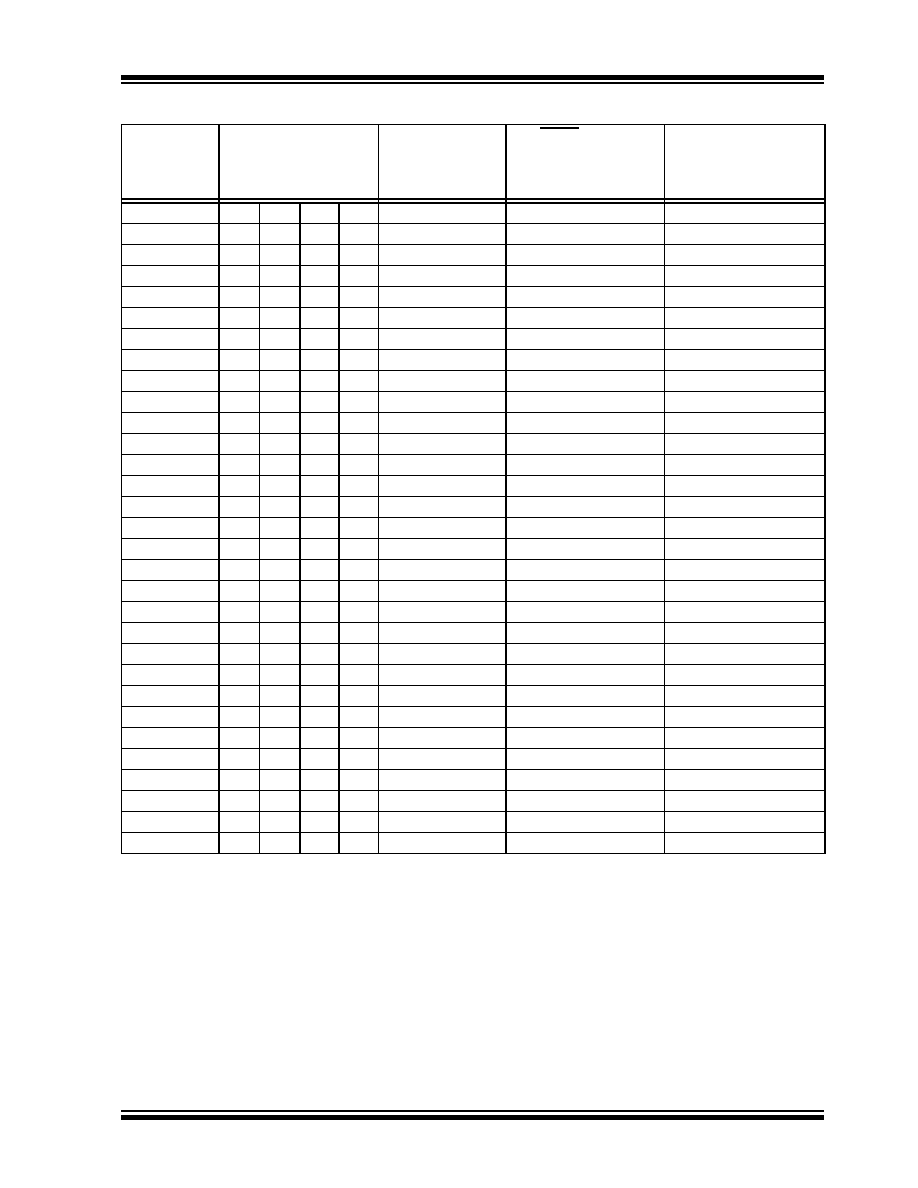
TABLE 5-4:
INITIALIZATION CONDITIONS FOR ALL REGISTERS (CONTINUED)
Register
Applicable Devices
Power-on Reset,
Brown-out Reset
MCLR Resets,
WDT Reset,
RESET Instruction,
Stack Resets
Wake-up via WDT
or Interrupt
Legend: u = unchanged, x = unknown, - = unimplemented bit, read as ‘0’, q = value depends on condition.
Shaded cells indicate conditions do not apply for the designated device.
Note 1:
One or more bits in the INTCONx or PIRx registers will be affected (to cause wake-up).
2:
When the wake-up is due to an interrupt and the GIEL or GIEH bit is set, the PC is loaded with the interrupt
vector (0008h or 0018h).
3:
When the wake-up is due to an interrupt and the GIEL or GIEH bit is set, the TOSU, TOSH and TOSL are
updated with the current value of the PC. The STKPTR is modified to point to the next location in the
hardware stack.
4:
See Table 5-3 for Reset value for specific condition.
5:
Bits 6 and 7 of PORTA, LATA and TRISA are enabled, depending on the oscillator mode selected. When
not enabled as PORTA pins, they are disabled and read ‘0’.
6:
This register reads all ‘0’s until ECAN technology is set up in Mode 1 or Mode 2.
相關(guān)PDF資料 |
PDF描述 |
|---|---|
| V48C28M75BF | CONVERTER MOD DC/DC 28V 75W |
| V48C28M75BL3 | CONVERTER MOD DC/DC 28V 75W |
| D38999/20MJ7SN | CONN RCPT 99POS WALL MNT W/SCKT |
| D38999/20JJ7SN | CONN RCPT 99POS WALL MNT W/SCKT |
| V48C24M75BL | CONVERTER MOD DC/DC 24V 75W |
相關(guān)代理商/技術(shù)參數(shù) |
參數(shù)描述 |
|---|---|
| MCP2510-IST | 制造商:MICROCHIP 制造商全稱:Microchip Technology 功能描述:Stand-Alone CAN Controller with SPI Interface |
| MCP2510I-ST | 制造商:MICROCHIP 制造商全稱:Microchip Technology 功能描述:Stand-Alone CAN Controller with SPIa?¢ Interface |
| MCP2510T-/P | 制造商:MICROCHIP 制造商全稱:Microchip Technology 功能描述:Stand-Alone CAN Controller with SPI⑩ Interface |
| MCP2510T-/SO | 制造商:MICROCHIP 制造商全稱:Microchip Technology 功能描述:Stand-Alone CAN Controller with SPI⑩ Interface |
| MCP2510T-/ST | 制造商:MICROCHIP 制造商全稱:Microchip Technology 功能描述:Stand-Alone CAN Controller with SPI⑩ Interface |
發(fā)布緊急采購,3分鐘左右您將得到回復。