- 您現(xiàn)在的位置:買(mǎi)賣(mài)IC網(wǎng) > PDF目錄181670 > MCJM1A-48P0D6-0.5 48 CONTACT(S), MALE, STRAIGHT TELECOM AND DATACOM CONNECTOR, SOLDER, PLUG PDF資料下載
參數(shù)資料
| 型號(hào): | MCJM1A-48P0D6-0.5 |
| 元件分類(lèi): | 電信和以太網(wǎng)連接器 |
| 英文描述: | 48 CONTACT(S), MALE, STRAIGHT TELECOM AND DATACOM CONNECTOR, SOLDER, PLUG |
| 文件頁(yè)數(shù): | 1/2頁(yè) |
| 文件大小: | 118K |
| 代理商: | MCJM1A-48P0D6-0.5 |
Catalog 1308638
Dimensions are in inches and
Dimensions are shown for
USA: 1-800-522-6752
South America: 55-11-3611-1514
Revised 8-05
millimeters unless otherwise
reference purposes only.
Canada: 1-905-470-4425
Hong Kong: 852-2735-1628
specified. Values in brackets
Specifications subject
Mexico: 01-800-733-8926
Japan: 81-44-844-8013
www.tycoelectronics.com
are metric equivalents.
to change.
C. America: 52-55-5-729-0425
UK: 44-141-810-8967
Rectangular Connectors
48
JACKMATE MCJM Series Metal Shell Center Jackscrew Connectors
Technical and Performance
Data for Metal Shell
Electrical
Contact Resistance — The average
mated contact resistance is 4 milliohms,
with a maximum value of 8 milliohms,
using standard 24 AWG solid copper
leads when measured directly behind the
crimp joints of the mated pin and socket
contacts. The average resistance value at
100 microvolts is 4.8 milliohms.
Dielectric Withstanding Voltage
(60 Hz rms room temperature) —
Solder Pots: 600 VAC at sea level; 150
VAC at 70,000 feet [21,336m].
Wire Terminations: 750 VAC at sea level;
200 VAC at 70,000 feet [21,336m].
Corrosion Resistance (Per MIL-
STD-202C, Method 101B, Condition
B) — Both mated and unmated samples
do not exceed the maximum allowable
contact resistance (8 milliohms) when
subjected to the 48 hour salt spray test.
Durability — The contact resistance
after 500 mating cycles is less than the
maximum allowable, 8 milliohms.
Insulation Resistance — Greater than
5,000 megohms at room temperature for
the materials listed under “Materials”.
Maximum Current Carrying
Capacity — No. 24 contact 3 amperes.
It must be recognized, however, that all
the wires to a connector will not carry
their maximum current under all envi-
ronmental conditions due to wire tem-
perature.
Mechanical
Contact Engaging & Separation
Forces — 8.0 oz. max. [2.22N] (eng.),
0.5 oz. min.[.14N] (sep.).
Environmental
Temperature Range (Operating) —
-67°F to 302°F [-55°C to 150°C] for
Diallyl Phthalate.
Vibration (Per MIL-STD-202C,
Method 204-A, Condition D) — No
discontinuity in excess of 1 sec. dur-
ing twelve 20 minute sweeps from 10 to
2000 CPS at .06 double amplitude or 20
G forces, whichever is less.
Materials
Insulator — Diallyl Phthalate per MIL-
M-14, Type SDG-F.
Contacts — Pin contact: copper alloy
and beryllium copper alloy make up the
complete construction; Socket contact:
copper alloy.
Body Shells — Pin body shell: stain-
less steel, Types 304, Condition A per
QQ-S-766; Socket body shell: aluminum
alloy per QQ-A-591, A-380 alloy.
Hardware — Corrosion resistant
stainless steel.
Finishes
Contacts — Standard finish is
0.000050 [0.00127] gold over copper
flash per MIL-G-45204, Type II.
Body Shells — Pin body shell: passi-
vated per MIL-F-14072 (E-300); Socket
body shell: electroless nickel per AMS
204, Class 3, except thickness is
0.001/0.0015 [0.025/0.038].
Hardware — Passivated per
QQ–P–35.
Note: Insulators are molded into
their metal shells —
No bonded joint is used.
*Standard material used unless
otherwise specified.
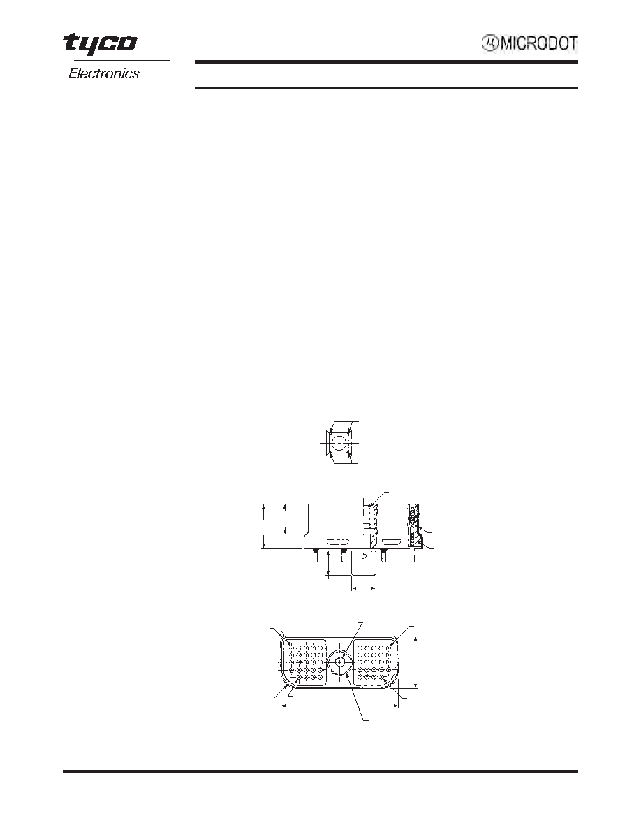
B Polarization
A Polarization
Insert
Shell
Contact Pin
Jackscrew 2-56 UNC-2B Thd.
.300
[7.62]
.199
[5.05]
.180
[4.57]
.187
[4.75]
.830
[21.08]
.125
[3.18]
.350
[8.89]
#41
#1
#48
Rad.
Typ.
.046
[1.17]
#10
Rad.
Typ.
.078
[1.98]
Hex
Socket
Jackscrew
Plug (Pin Side)
Shell Type M1
相關(guān)PDF資料 |
PDF描述 |
|---|---|
| MCJM1A-48P0D7-0.5 | 48 CONTACT(S), MALE, STRAIGHT TELECOM AND DATACOM CONNECTOR, SOLDER, PLUG |
| MCJM1A-48P0D8-0.5 | 48 CONTACT(S), MALE, STRAIGHT TELECOM AND DATACOM CONNECTOR, SOLDER, PLUG |
| MCJM1A-48P0D9-0.5 | 48 CONTACT(S), MALE, STRAIGHT TELECOM AND DATACOM CONNECTOR, SOLDER, PLUG |
| MCJM1A-48P0G1-0.5 | 48 CONTACT(S), MALE, STRAIGHT TELECOM AND DATACOM CONNECTOR, SOLDER, PLUG |
| MCJM1A-48P0G2-0.5 | 48 CONTACT(S), MALE, STRAIGHT TELECOM AND DATACOM CONNECTOR, SOLDER, PLUG |
相關(guān)代理商/技術(shù)參數(shù) |
參數(shù)描述 |
|---|---|
| MCJR1D00 | 制造商:Veeder-Root Company 功能描述: |
| MCJR1S00 | 制造商:Veeder-Root Company 功能描述: 制造商:DANAHER - INDUSTRIAL/SPECIALTY 功能描述:MULTIFUNCTION COUNTER, No. of Digits / Alpha:8, Digit Height:7.6mm, Power Consum |
| MCJR2D00 | 制造商:DANAHER SPECIALTY PRODUCTS 功能描述:Counter, programmable, 2 preset, predetermining, 10-26VDC, 5 digit |
| MCJR2S00 | 制造商:DANAHER SPECIALTY PRODUCTS 功能描述:COUNTER, MAXJR COUNT 2; 115/230 VAC 制造商:DANAHER CONTROLS 功能描述:MULTIFUNCTION COUNTER 制造商:DANAHER CONTROLS 功能描述:MULTIFUNCTION COUNTER; No. of Digits / Alpha:5; Digit Height:14.2mm; Power Consumption:6VA; Panel Cutout Height:45.21mm; Panel Cutout Width:90.93mm; Counting Speed:10kHz; Operating Temperature Min:0C; Operating Temperature Max:50C ;RoHS Compliant: NA |
| MCK0209 | 制造商:FCI 功能描述: |
發(fā)布緊急采購(gòu),3分鐘左右您將得到回復(fù)。