- 您現(xiàn)在的位置:買賣IC網(wǎng) > PDF目錄45223 > MC68HC05SR3FB (MOTOROLA INC) 8-BIT, MROM, 2 MHz, MICROCONTROLLER, PQFP44 PDF資料下載
參數(shù)資料
| 型號(hào): | MC68HC05SR3FB |
| 廠商: | MOTOROLA INC |
| 元件分類: | 微控制器/微處理器 |
| 英文描述: | 8-BIT, MROM, 2 MHz, MICROCONTROLLER, PQFP44 |
| 封裝: | QFP-44 |
| 文件頁數(shù): | 87/96頁 |
| 文件大?。?/td> | 612K |
| 代理商: | MC68HC05SR3FB |
第1頁第2頁第3頁第4頁第5頁第6頁第7頁第8頁第9頁第10頁第11頁第12頁第13頁第14頁第15頁第16頁第17頁第18頁第19頁第20頁第21頁第22頁第23頁第24頁第25頁第26頁第27頁第28頁第29頁第30頁第31頁第32頁第33頁第34頁第35頁第36頁第37頁第38頁第39頁第40頁第41頁第42頁第43頁第44頁第45頁第46頁第47頁第48頁第49頁第50頁第51頁第52頁第53頁第54頁第55頁第56頁第57頁第58頁第59頁第60頁第61頁第62頁第63頁第64頁第65頁第66頁第67頁第68頁第69頁第70頁第71頁第72頁第73頁第74頁第75頁第76頁第77頁第78頁第79頁第80頁第81頁第82頁第83頁第84頁第85頁第86頁當(dāng)前第87頁第88頁第89頁第90頁第91頁第92頁第93頁第94頁第95頁第96頁
MOTOROLA
A-2
MC68HC05SR3
MC68HC705SR3
A
A.2
Modes of Operation
The MC68HC705SR3 has two modes of operation – user mode and EPROM bootstrap mode.
Table A-1 shows the conditions required to enter each mode on the rising edge of RESET.
A.3
User Mode
The normal operating mode of the MC68HC705SR3 is the user mode. User mode will be entered
on the rising edge of RESET when the VPP and PB1 pins are between VSS and VDD.
Warning: In the MC68HC705SR3, all vectors are fetched from EPROM in user mode; therefore,
the EPROM must be programmed (via the bootstrap mode) before the device is
powered up in user mode.
A.4
Bootstrap Mode
The bootstrap mode is provided as a mean of self-programming MC68HC705SR3 EPROM with
minimal circuitry, and can only run in the crystal oscillator mode. Bootstrap mode will be entered
on the rising edge of RESET when the VPP pin is at VTST (2×VDD) and PB1 pin is at VDD. Once in
the bootstrap mode, PB1 can then be used for other purposes. After entering the bootstrap mode,
CPU branches to the bootstrap program and carries out the EPROM programming routine. The
user EPROM consists of 3840 bytes, from location $1000 to $1EFF.
This program handles copying of user code from an external EPROM into the on-chip EPROM.
The bootstrap function does not have to be done from an external EPROM, but it may be done
from a host.
The user code must be a one-to-one correspondence with the internal EPROM addresses.
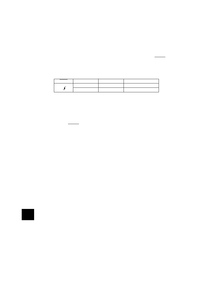
Table A-1 MC68HC705SR3 Operating Mode Entry Conditions
RESET
VPP
PB1
MODE
VSS to VDD
USER
VTST
VDD
BOOTSTRAP
VTST=2×VDD
5V
TPG
86
相關(guān)PDF資料 |
PDF描述 |
|---|---|
| MC68HC05SR3P | 8-BIT, MROM, 2 MHz, MICROCONTROLLER, PDIP40 |
| MC68HC705SR3CFB | 8-BIT, OTPROM, 2 MHz, MICROCONTROLLER, PQFP44 |
| MC68HC05SU3AP | 8-BIT, MROM, 2 MHz, MICROCONTROLLER, PDIP40 |
| MC68HC05SU3AFB | 8-BIT, MROM, 2 MHz, MICROCONTROLLER, PQFP44 |
| MC68HC05SU3AB | 8-BIT, MROM, 2 MHz, MICROCONTROLLER, PDIP42 |
相關(guān)代理商/技術(shù)參數(shù) |
參數(shù)描述 |
|---|---|
| MC68HC05SU3A | 制造商:FREESCALE 制造商全稱:Freescale Semiconductor, Inc 功能描述:Fully static chip design featuring the industry standard 8-bit M68HC05 core |
| MC68HC05T16 | 制造商:FREESCALE 制造商全稱:Freescale Semiconductor, Inc 功能描述:High-density complementary metal oxide semiconductor (HCMOS) microcontroller unit |
| MC68HC05V12 | 制造商:FREESCALE 制造商全稱:Freescale Semiconductor, Inc 功能描述:HCMOS Microcontreller Unit |
| MC68HC05V12CFN | 制造商:FREESCALE 制造商全稱:Freescale Semiconductor, Inc 功能描述:General Release Specification |
| MC68HC05X16 | 制造商:FREESCALE 制造商全稱:Freescale Semiconductor, Inc 功能描述:High-density complementary metal oxide semiconductor HCMOS) microcontroller unit |
發(fā)布緊急采購(gòu),3分鐘左右您將得到回復(fù)。